Wave energy prime mover

A prime mover and wave energy technology, applied in the field of power machinery, can solve the problems of large area, environmental pollution, energy shortage, etc., and achieve the effects of protecting land resources, reducing production costs, and eliminating the greenhouse effect

Inactive Publication Date: 2003-06-04
赵世友
View PDF0 Cites 5 Cited by
  • Summary
  • Abstract
  • Description
  • Claims
  • Application Information

AI Technical Summary

Problems solved by technology

[0003] The purpose of the present invention is to provide a wave energy prime mover to solve the problems of energy shortage, greenhouse effect, environmental pollution, large investment, high cost, and large occupied area in the prior art.

Method used


Image

  • Wave energy prime mover
  • Wave energy prime mover

Examples


Embodiment Construction

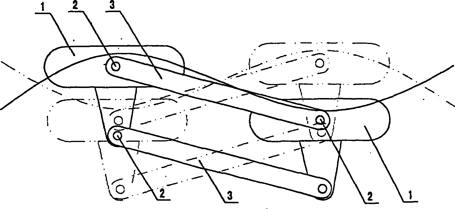
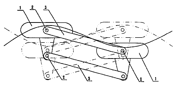
[0017] The present invention includes buoyancy tanks, connecting rods and connecting rod shafts, wherein two identical buoyant tanks 1 are spaced apart and arranged in parallel, two buoyant tanks 1 are respectively provided with two-way ratchet transmissions, and two connecting rods 3 pass through the connecting rod shafts 2 Connect with two floating tanks 1 respectively, the connecting rod shaft 2 can rotate in the connecting rod shaft hole of the floating tank 1, and the shaft end of the connecting rod shaft 2 stretches into the floating tank 1 and connects the input shaft of the two-way ratchet speed changer. The two floating tanks 1 can move up and down relative to the waves, and the output shaft of the two-way ratchet transmission can output torque.

[0018] When working, the wave energy prime mover is put into the water, and it just floats on the water surface due to the effect of the two pontoon boxes. Waves have crests and troughs, and the two buoys fluctuate relative ...


PUM


Abstract

The wave energy prime mover is one power machine converting wave energy into mechanical energy. The fluctuant waves are utilized to drive some machine to rotate and the rotating machine then drives power generator or ship. The present invention includes floating boxes, link rods and link rod shaft. Inside two parallel and spaced floating boxes, there are two-way ratchet wheel speed variators, twolink rods are connected to two floating boxes via the link rod shaft, and the link rod shaft has ends extending into the floating boxes to connect the input ends of the two-way ratchet wheel speed variators. The present invention is used in sea wave generating electricity and driving ship.

Description

technical field [0001] The invention relates to a power machine, in particular to a power machine which converts wave energy into mechanical energy. Background technique [0002] With the development of modern industrial production, the demand for energy is increasing day by day. The bio-fossil energy represented by coal and oil can no longer meet the demand and is gradually exhausted. Moreover, most of these power machines using coal and oil as energy have environmental pollution problems. , the carbon dioxide produced during combustion accelerates the earth's greenhouse effect, which leads to temperature rise, disaster increase, sea level rise, ecological environment deterioration and other consequences. If human beings do not develop new energy in time, they will face serious energy crisis and survival crisis. Countries around the world are competing to find new energy sources, and solar energy, wind energy, hydraulic power, tides, etc. all have the goal of developing ne...

Claims


Application Information

Patent Timeline
Patent Type & Authority Applications(China)
IPC IPC(8): F03B13/12
Inventor 赵世友
Owner 赵世友
Why Eureka
Try Eureka