

Static protection circuit
A technology for electrostatic protection and circuits, applied in circuits, electrical components, electrical solid devices, etc., can solve problems such as circuit reliability problems
- Summary
- Abstract
- Description
- Claims
- Application Information
AI Technical Summary
Problems solved by technology
Method used
Image

Examples
Embodiment Construction
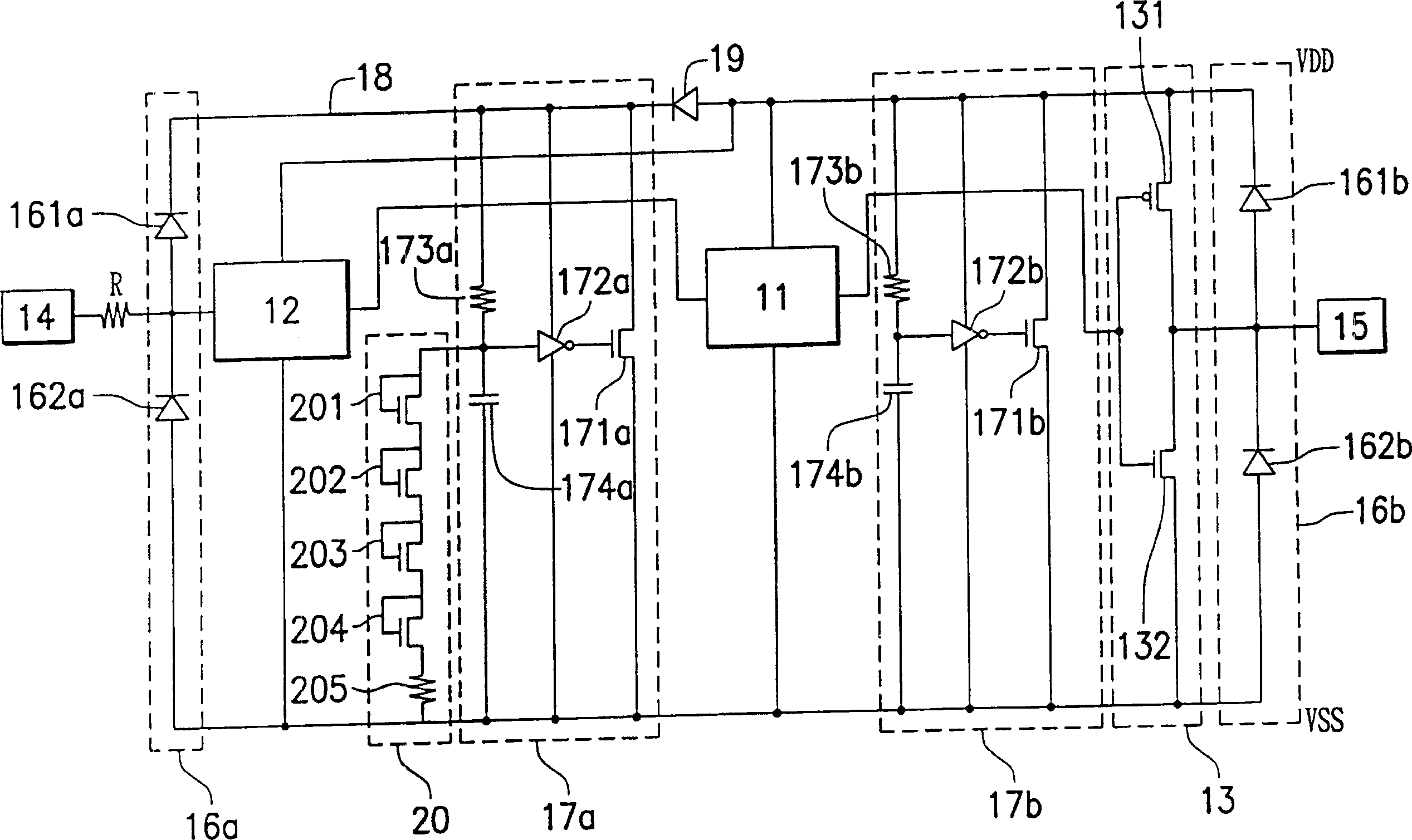
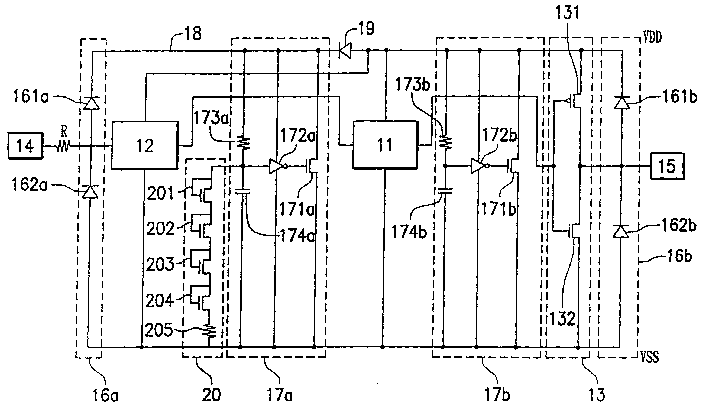
[0029] figure 2 It shows the electrostatic protection circuit in one embodiment of the present invention. figure 2 neutralize figure 1 The same elements are given the same symbols and will not be described in detail.
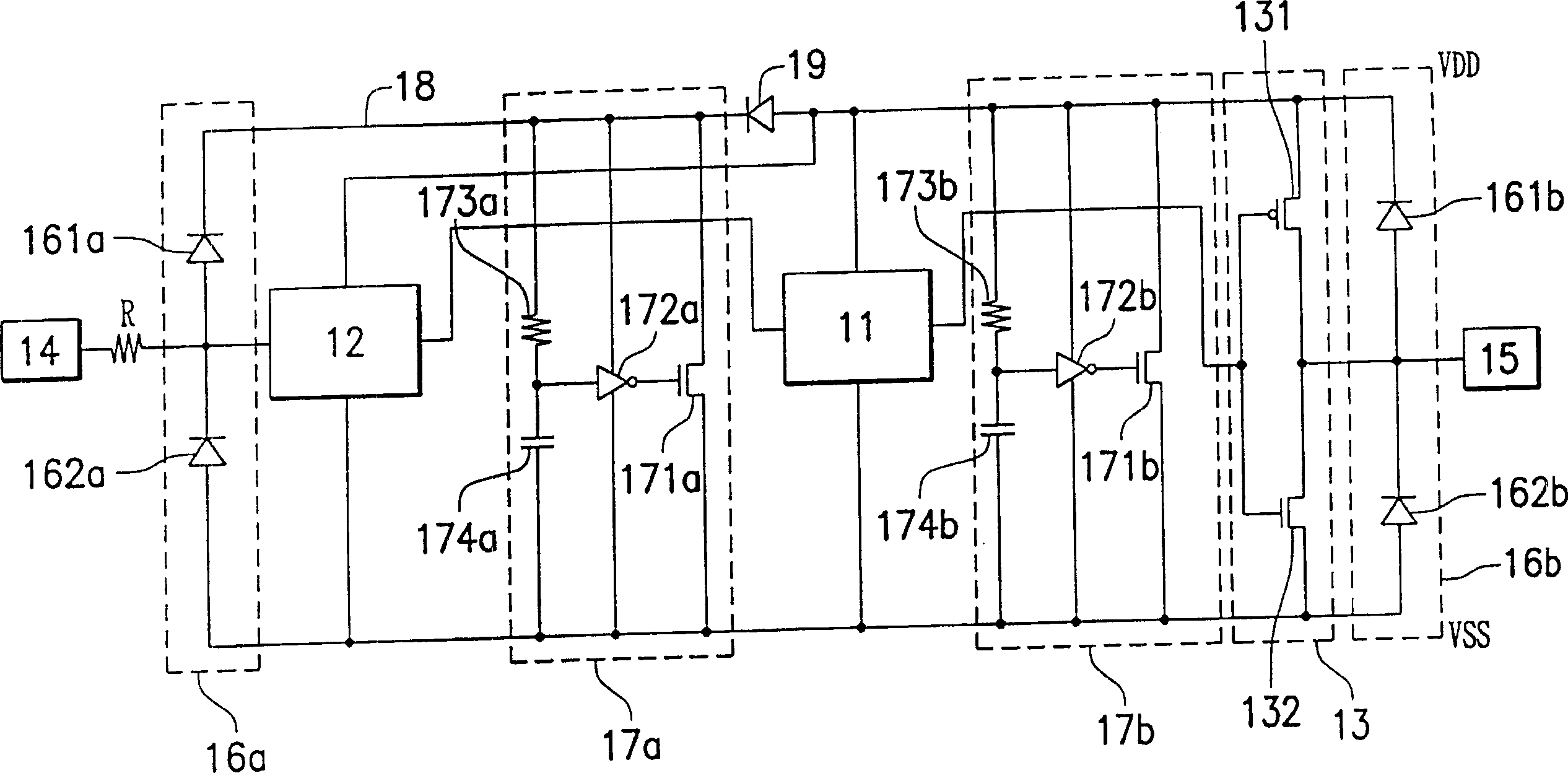
[0030] figure 2 Including a main protected internal circuit 11, a 5-volt to 3-volt converter 12, an output circuit 13, an input pad (pad) 14, an output pad 15, four electrostatic protection circuits 16a, 16b, 17a, 17b, a floating ESD bus 18 , a diode 19 , a resistor R and a voltage clamper 20 . In addition, all active components are driven by two voltage sources providing VDD and VSS voltages.
[0031] Wherein, since the VDD voltage used by the internal circuit 11 is 3 volts, and the amplitude of the input signal received by the input pad 14 is 5 volts, the 5-volt to 3-volt converter will receive the input signal via the input pad 14 The amplitude is reduced to 3 volts to accommodate the internal circuit 11. After the internal circuit 11 receives the re...
PUM
 Abstract
Description
Claims
Application Information