Small ion-decomposing melting furnace

A melting furnace and ion technology, applied in furnaces, incinerators, electric furnace heating and other directions, can solve the problems of difficulty in moving and troublesome processing, and achieve the effects of increasing plasma concentration, decomposition efficiency and ion concentration.

Inactive Publication Date: 2003-07-23
菊地 政市 +2
View PDF0 Cites 10 Cited by
  • Summary
  • Abstract
  • Description
  • Claims
  • Application Information

AI Technical Summary

Problems solved by technology

[0004] The above-mentioned incinerator has the advantage of being able to quickly process the incineration target and has a high processing capacity, but has the difficulty of moving due to its large size and is troublesome for processing, although it has no particular disadvantages.
[0005] In addition to

Method used


Image

  • Small ion-decomposing melting furnace
  • Small ion-decomposing melting furnace
  • Small ion-decomposing melting furnace

Examples


Embodiment Construction

[0019] (Embodiment 1)

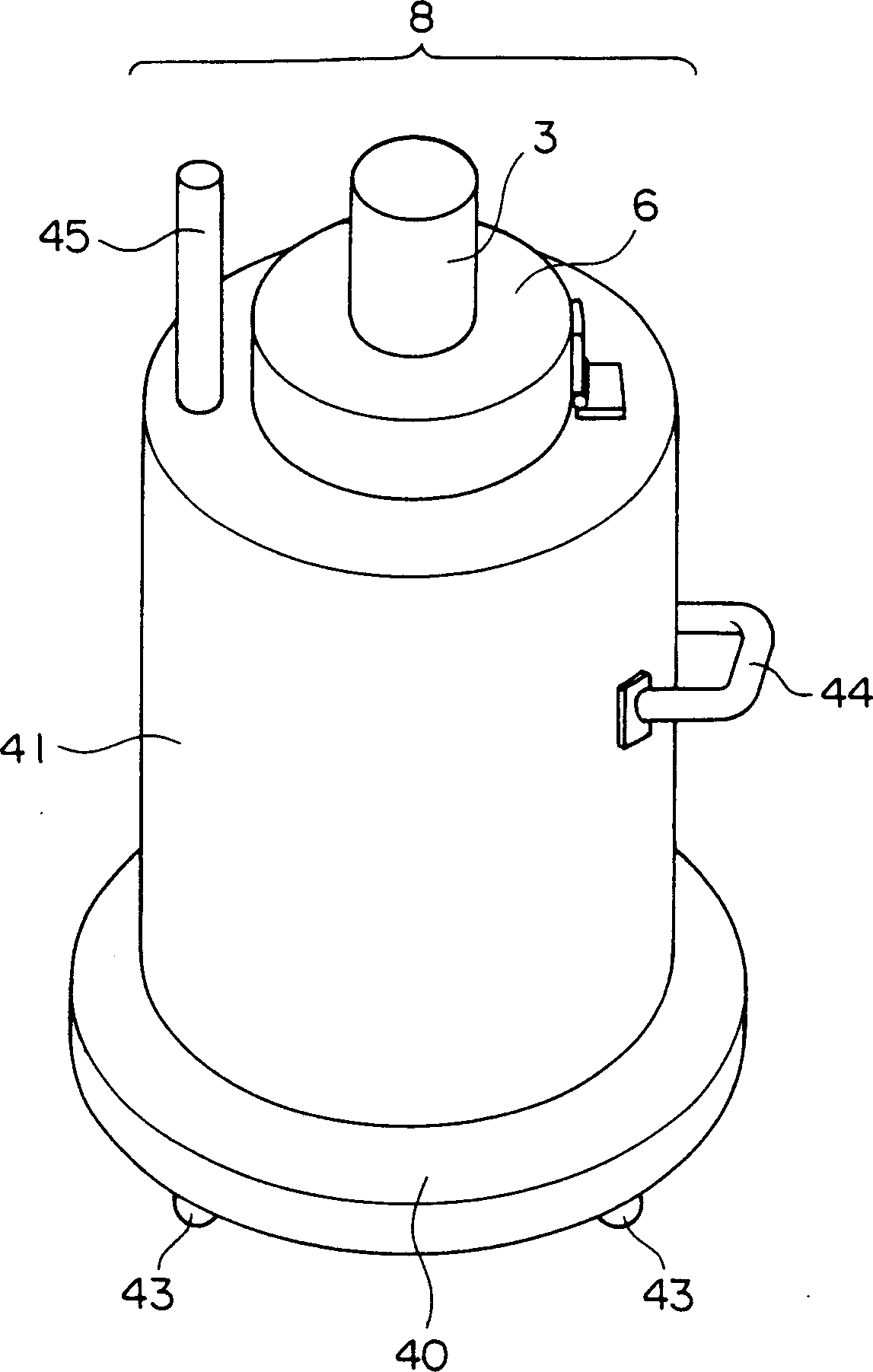
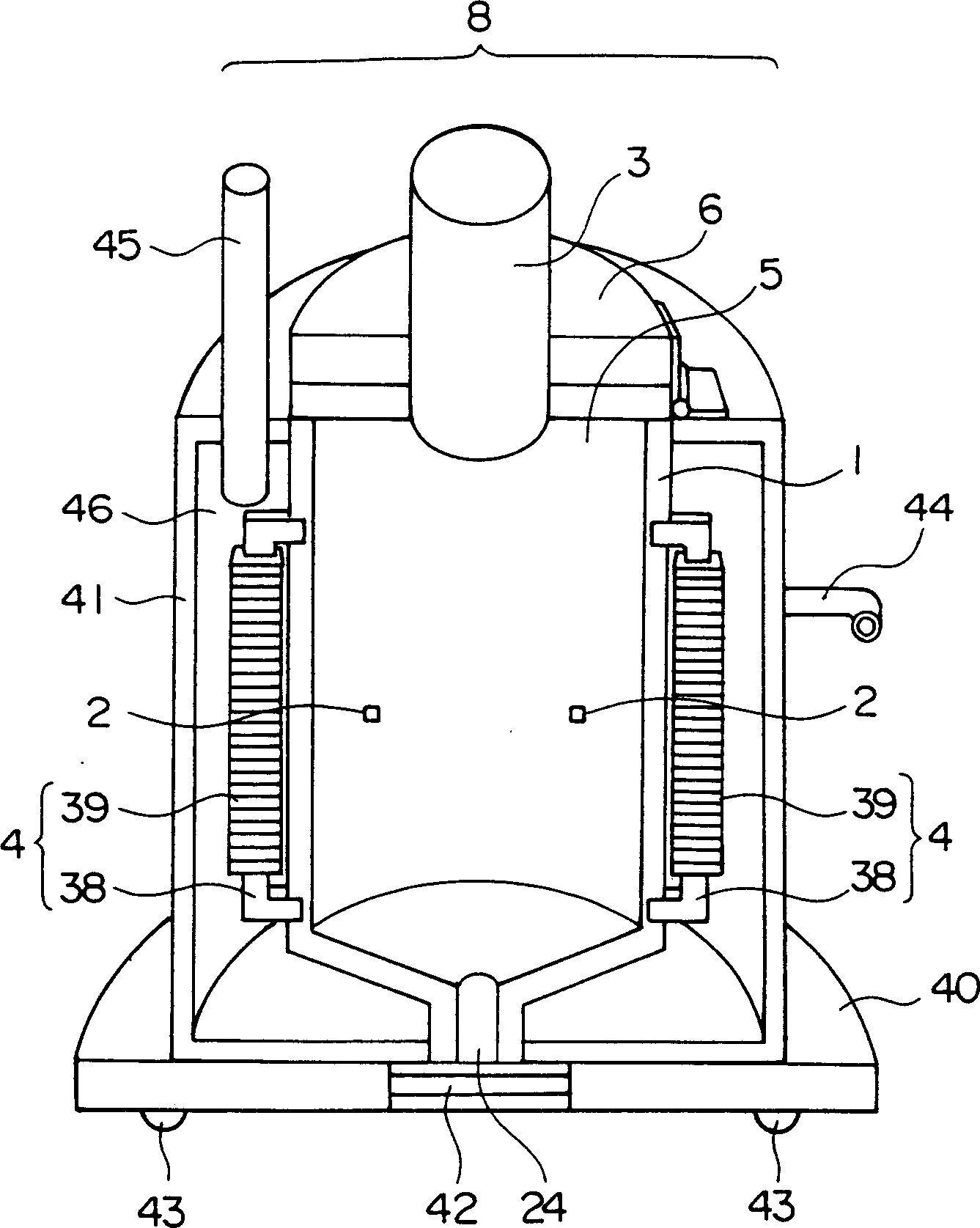
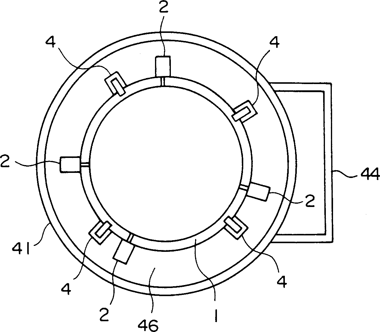
[0020] based on Figure 1 to Figure 8 A first embodiment of the small ion decomposition type melting furnace of the present invention will be described. The small-sized ion decomposition type melting furnace 8 of these figures is that four magnetrons 2 are set on the wall around the incinerator body 1, and ionizers are installed downwards on the cover 6 covering the input port 5 on the top of the incinerator body 1. The flame generator (ion furnace) 3 is provided with six tokamaks 4 on the same incinerator body 1 . The aforementioned four magnetrons 2 are as image 3 The non-facing positions of the walls around the incinerator body 1 are installed as shown, and the aforementioned six tokamak 4 are as follows image 3 As shown, four are set on the periphery of the incinerator body 1, such as Figure 5 As shown, one is respectively arranged on the upper part and the lower part of the incinerator body.

[0021] The furnace wall 20 of the incinerator b...


PUM


Abstract

A microwave-supplying magnetron and an ion burner are provided in an incinerator body, microwave from the magnetron and ion flame from the ion burner are resonated with each other to heat the inside of the incinerator body to high temperature, and wastes in the incinerator body are decomposed and melted by activated ions (+)(-). A tokamak is provided on the outer side of the incinerator body to reflect charged particles (radiation) and electromagnetic waves for focussing to the center of the inside of the incinerator body, thereby increasing an on concentration, a plasma concentration and a decomposing efficiency. Both or one of crystal and an acceptor-level additive are mixed into the furnace wall of the incinerator body.

Description

technical field [0001] The invention relates to a small-sized ion decomposition type melting furnace which mainly takes daily life garbage, plastics, waste liquid, waste oil and other garbage, and can also incinerate and melt waste such as metal. Background technique [0002] For incinerators that melt and process incineration objects such as garbage and incineration ash at high temperatures above 1,000°C, there are various methods such as surface method, gyratory flow method, bottom coke method, arc method, plasma method, resistance method, and induction heating method. way. The melting temperatures of these systems are all about 1000°C to 1500°C. [0003] As an incinerator capable of generating a higher temperature, there is an incinerator of Patent No. 3,034,461, which was previously developed and applied for by the present inventor. In this kind of incinerator, starting from the ion flame generating device (ion furnace) installed in the incinerator body until the keros...

Claims


Application Information

Patent Timeline
IPC IPC(8): F23G5/00F23C15/00F23C99/00F23G5/08F27D11/12H05B6/80
CPCF23G5/085H05B6/80F23G2204/203H05B2206/046F23G2900/50006F23G2204/201F23C99/001H05B2206/045
Inventor 菊地政市
Owner 菊地 政市
Why Eureka
Try Eureka