Apparatus and method for radiation detection

A technology of equipment and detectors, applied in the directions of radiation measurement, radiation intensity measurement, X/γ/cosmic radiation measurement, etc.

Inactive Publication Date: 2003-07-30
XCOUNTER
View PDF0 Cites 4 Cited by
  • Summary
  • Abstract
  • Description
  • Claims
  • Application Information

AI Technical Summary

Problems solved by technology

[0005] However, these detectors, which involve interactions between ph

Method used


Image

  • Apparatus and method for radiation detection
  • Apparatus and method for radiation detection
  • Apparatus and method for radiation detection

Examples


Embodiment Construction

[0020] In the following description, for the purpose of explanation and not limitation, detailed details such as specific dimensions and materials are described in order to provide a thorough understanding of the present invention. However, it will be clear to those skilled in the art that the present invention can be implemented with other embodiments that deviate from these specific details.

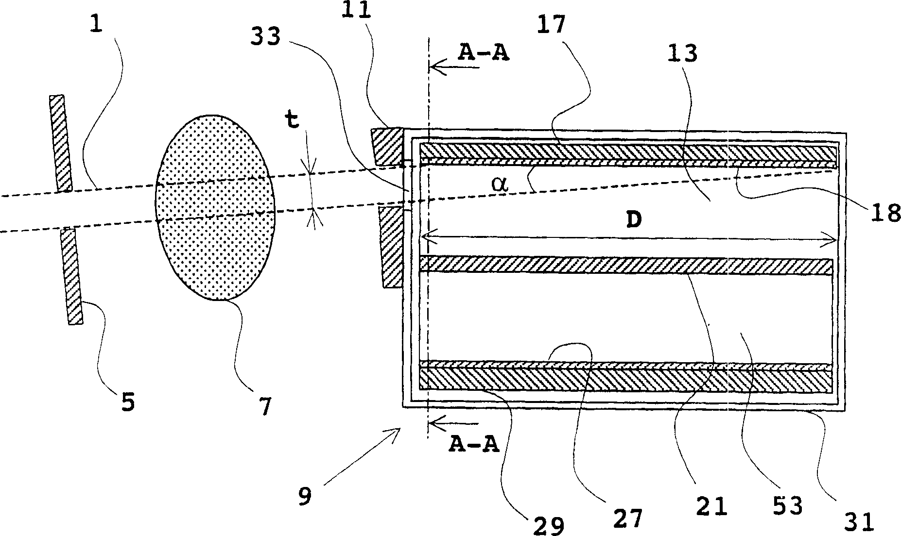
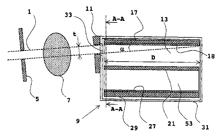
[0021] reference figure 1 Describing a preferred embodiment of the present invention, a cross-sectional view in a plane orthogonal to the plane of the planar X-ray beam 1 is used to briefly illustrate the apparatus for planar beam radiography.

[0022] The device includes an X-ray source (not shown), which together with the collimator window 5 generates a fan-shaped X-ray beam 1 for illuminating the object to be imaged. The collimator window 5 can be replaced by other devices that form a substantially flat X-ray beam, such as an X-ray diffractive mirror or an X-ray lens.

[0023] The emit...


PUM


Abstract

The present invention relates to an apparatus for detection of radiation comprising a photocathode layer adapted to release photoelectrons in dependence on incident radiation; a radiation entrance arranged such that a beam of radiation can be entered into the apparatus through said radiation entrance and can impinge on said photocathode layer at grazing incidence; an electron avalanche amplifier adapted to avalanche amplify photoelectrons released from said photocathode layer; and a readout arrangement adapted to detect avalanche amplified electrons from said amplifier. The invention further relates to a corresponding method for detection of ionizing radiation and to an arrangement for use in planar beam radiography comprising the detector apparatus.

Description

Technical field [0001] The present invention generally relates to an apparatus and method for detecting radiation. [0002] The present invention can be used in various fields including medical radiology, computer tomography (CT), microscopy, and non-invasive testing. Background technique [0003] Gas detectors are generally very attractive where the photon energy is less than about 10 KeV. The main advantage of gas detectors is that they are cheaper to manufacture than solid-state detectors, and they can use gas amplification to greatly amplify the signal amplitude (several orders of magnitude). However, when the energy exceeds 10KeV, the gas detector is not very attractive, because the blocking ability of the gas decreases rapidly with the increase of photon energy. Due to the parallax of the conversion point of the generally divergent radiation incident beam and the so-called extended trajectory of long-distance photons as a result of X-ray absorption, a severe reduction in sp...

Claims


Application Information

Patent Timeline
IPC IPC(8): G01N23/04G01T1/00G01T1/18G01T1/185G01T1/28H01J29/38H01J43/02H01J47/06
CPCH01J43/02G01T1/185
Inventor T·弗兰克V·佩斯科夫
Owner XCOUNTER
Why Eureka
Try Eureka