
Cross thin wall pipe-sinking device for vibration pipe-sinking pile-dilling machine and pile-filling method thereof

A technology of immersed cast-in-place piles and immersed pipe piles is applied in sheet pile wall, building, infrastructure engineering and other directions, which can solve the problems of increasing project cost, low bearing capacity, small side friction resistance, etc., so as to reduce project cost and improve The effect of carrying capacity

Inactive Publication Date: 2003-08-06
INST OF ROCK AND SOIL MECHANICS - CHINESE ACAD OF SCI
View PDF0 Cites 18 Cited by
  • Summary
  • Abstract
  • Description
  • Claims
  • Application Information

AI Technical Summary

Problems solved by technology

Its shortcoming is that, because the surface area of ​​the pile per unit volume of the cast-in-place pile is small, the lateral frictional resistance is small, resulting in a low bearing capacity per unit volume of the cast-in-place pile. Therefore, more materials are used to achieve the same bearing capacity. In the reinforcement of weak foundation, the project cost will be greatly increased

Method used


Image

  • Cross thin wall pipe-sinking device for vibration pipe-sinking pile-dilling machine and pile-filling method thereof
  • Cross thin wall pipe-sinking device for vibration pipe-sinking pile-dilling machine and pile-filling method thereof
  • Cross thin wall pipe-sinking device for vibration pipe-sinking pile-dilling machine and pile-filling method thereof

Examples


Embodiment Construction

[0020] The present invention will be further described below in conjunction with the accompanying drawings.

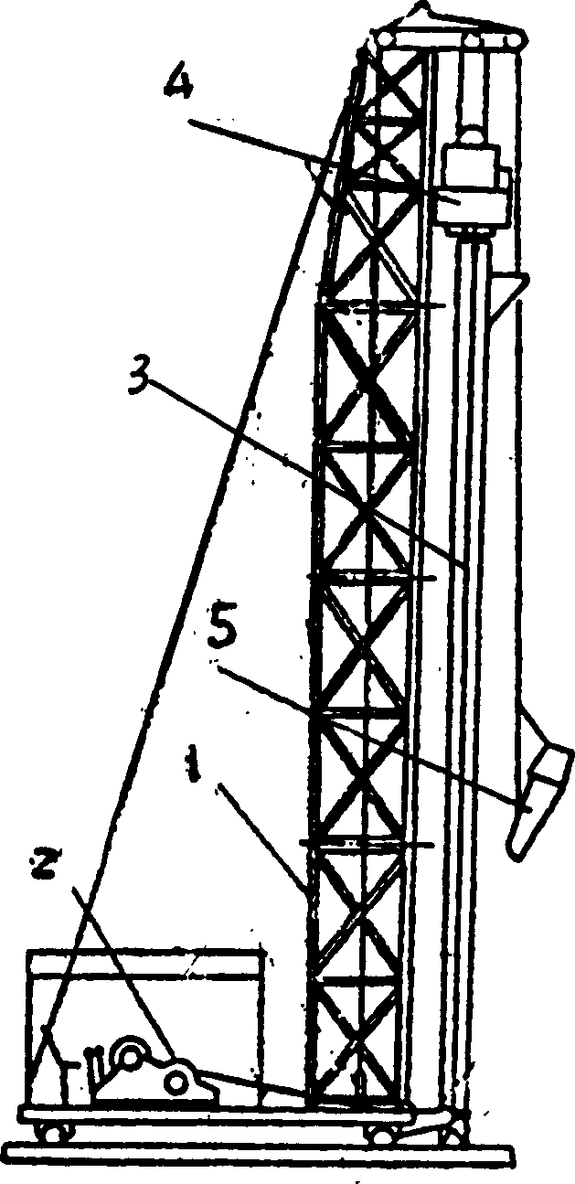
[0021] Depend on figure 1 It can be seen that the vibrating pipe sinking pile machine is composed of five parts: a frame 1, a hoist 2, an immersed pipe 3, a vibrating hammer 4 and a bucket 5. Among them, the frame 1 plays the role of supporting the hoist, the sinking tube with the valve pile tip, the vibrating hammer and the bucket; the hoist 2 is the power equipment for the pile sinking tube and the bucket to lift; Under the action of the vibrating hammer, the pipe 3 can pass through the general cohesive soil, silt soil, silty soil, silt, loose to medium-density sandy soil and artificial filling soil, and then pour concrete, and pull out the pile while vibrating The equipment; the vibratory hammer 4 has the dual functions of sinking the pipe and pulling the pile; the concrete is poured into the pile pipe through the bucket 5.

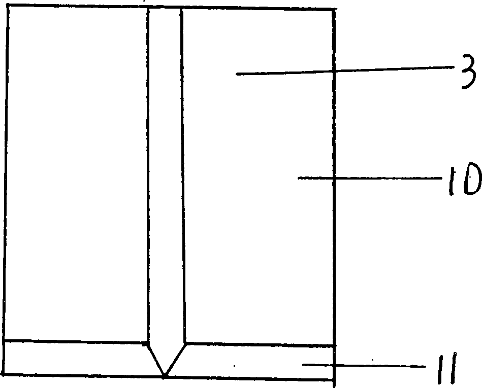
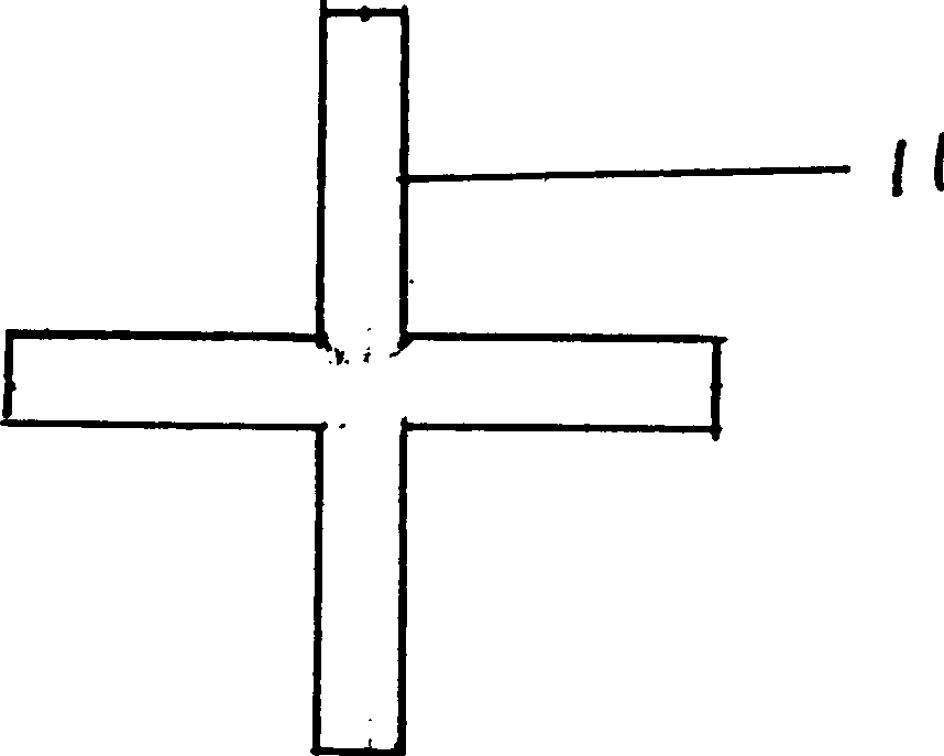
[0022] Depend on figure 2 , image ...


PUM


Abstract

The present invention discloses a cross thin-wall pipe-sinking equipment for vibration-pipe sinking pile-filling machine and its application method. Said cross thin-wall pipe-sinking equipment is formed from pipe body and flapper pipe point. The pipe body and cross flapper pipe point are connected by means of hinge, the cross-section of the pipe body is a cross form, when the cross thin-wall concrete pipe is used for strengthening soft ground base, firstly the cross thin-wall pipe-sinking equipment is mounted on the vibration pipe-sinking pile-making machine, the cross thin-wall pipe can be wedge-inserted into soft ground base to reach the design depth, then the concrete is poured into the cross thin-wall sunken pipe, the sunken pipe is vibrated while drawing out the sunken pipe until thecross thin-wall concrete pile is completely poured.

Description

Technical field: [0001] The invention relates to a tube sinking pile machine, more particularly to a tube sinking device of a vibrating tube sinking pile machine. The invention also relates to a method for pouring cross thin-walled concrete piles using the cross thin-wall immersed pipe device. Background technique: [0002] At present, cast-in-place piles are mostly used to strengthen weak foundations, and can be divided into cast-in-place piles with vibration sinking, hammering cast-in-place piles and static pressure cast-in-place piles according to their hole-forming methods. When using immersed tube piles to strengthen weak foundations, use a vibrating tube sinking pile driver, or a hammering sinking tube pile driver, or a static pressure sinking tube pile driver, respectively with a valve-type pile tip or a tapered sealing pile tip, Or a steel pipe with a prefabricated reinforced concrete pile point is sunk into the soil, and then the cast-in-place pile is formed by pul...

Claims


Application Information

Patent Timeline
IPC IPC(8): E02D5/38E02D5/66E02D7/18
Inventor 姚海林程平
Owner INST OF ROCK AND SOIL MECHANICS - CHINESE ACAD OF SCI
Learn More