Supercharge Your Innovation With Domain-Expert AI Agents!

Shape measurer with adjustable image magnifying power in two axes

A technology of magnification and measuring device, applied in the direction of measuring device, instrument, etc., can solve the problems of difficulty, no use value, shortened field of view, etc.

Inactive Publication Date: 2003-08-20
IND TECH RES INST
View PDF2 Cites 1 Cited by
  • Summary
  • Abstract
  • Description
  • Claims
  • Application Information

AI Technical Summary

Problems solved by technology

[0003] Existing methods can already obtain higher resolution in the direction of projected light, but they cannot solve the fact that the resolution will become lower and lower as the distance from the light source gets farther and farther away. The problem of uneven resolution occurs when the When the resolution at short distances is sufficient, the resolution at long distances is insufficient; in addition, in the prior art, the resolution perpendicular to the direction of projected light is determined by the parameters of the CCD camera, so the selected focal length and object distance have determined the direction resolution
If you want to change the resolution perpendicular to the projected light direction, you can only change the object distance or focal length, but usually a shape measuring device has its desired object distance in operation, so the range of object distance that can be adjusted is relatively limited. Therefore, the focal length of the objective lens will probably be changed; whether it is to change the object distance or the focal length, the resolution of the projected light direction will also change accordingly, so it is necessary to change the anisotropic or anamorphic lens group parameter
Since the focal length of the objective lens directly determines the resolution of one axis, in fact, based on cost considerations, most of the imaging lenses use commercially available fixed-focus lenses, such as monitor lenses, whose focal length value is only a certain value, so the design must meet Two-axis resolution is difficult
[0004] like figure 1 Shown is a schematic diagram of the resolution of the existing non-modulated image magnification. A projected light plane 11 is projected onto the surface of an object 20 to be measured, and the situation presented by the reflected light 7 captured by the equidistant CCD pixels is completely Without adjusting the magnification of the image, the projected light direction has a fairly large field of view, but the resolution at the long-distance drops rapidly, and because the depth of field of the general imaging objective lens is very limited, the long-distance measurement accuracy is very poor, and it is almost useless
[0005] like figure 2 Shown is the existing U.S. Patent (No. 6,046,812) using a cylindrical mirror to improve the resolution schematic diagram, with a projected light plane 11 projected onto the surface of an object 20 to be measured, and the reflected light 7 captured by its equidistant CCD pixels The presented situation, where the use of cylindrical mirrors to shorten the field of view in the direction of the projected light, improves the resolution, but the resolution at the far end is still much lower than that at the near end

Method used


Image

  • Shape measurer with adjustable image magnifying power in two axes
  • Shape measurer with adjustable image magnifying power in two axes
  • Shape measurer with adjustable image magnifying power in two axes

Examples


no. 1 example

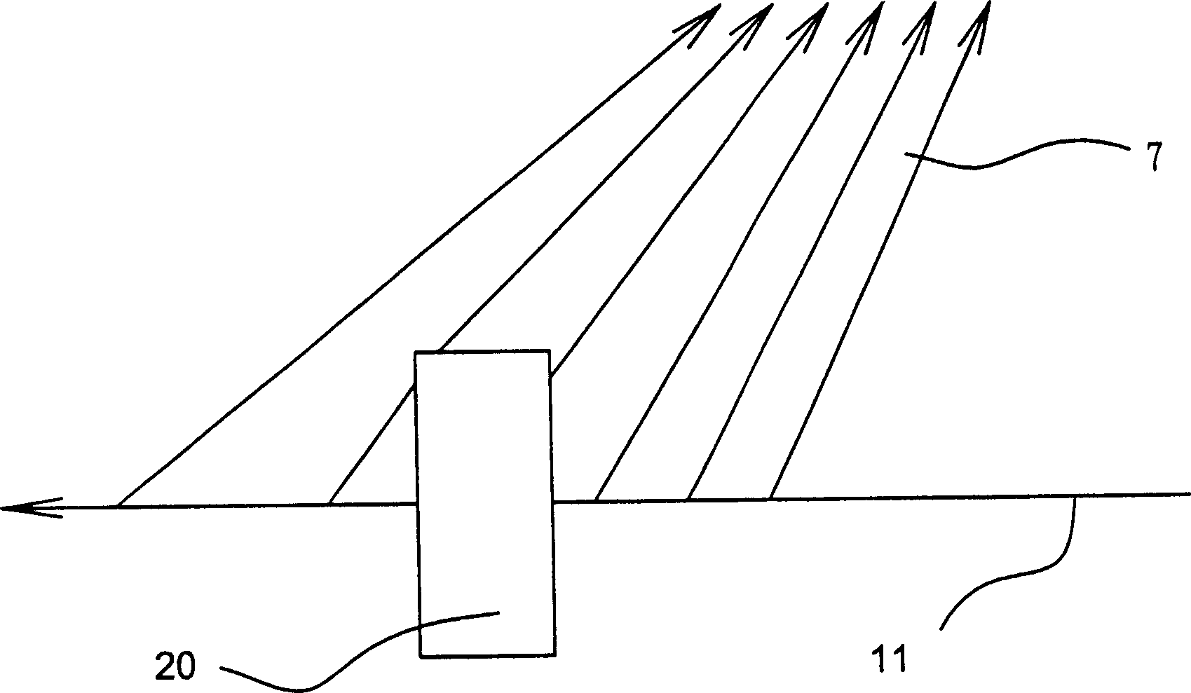
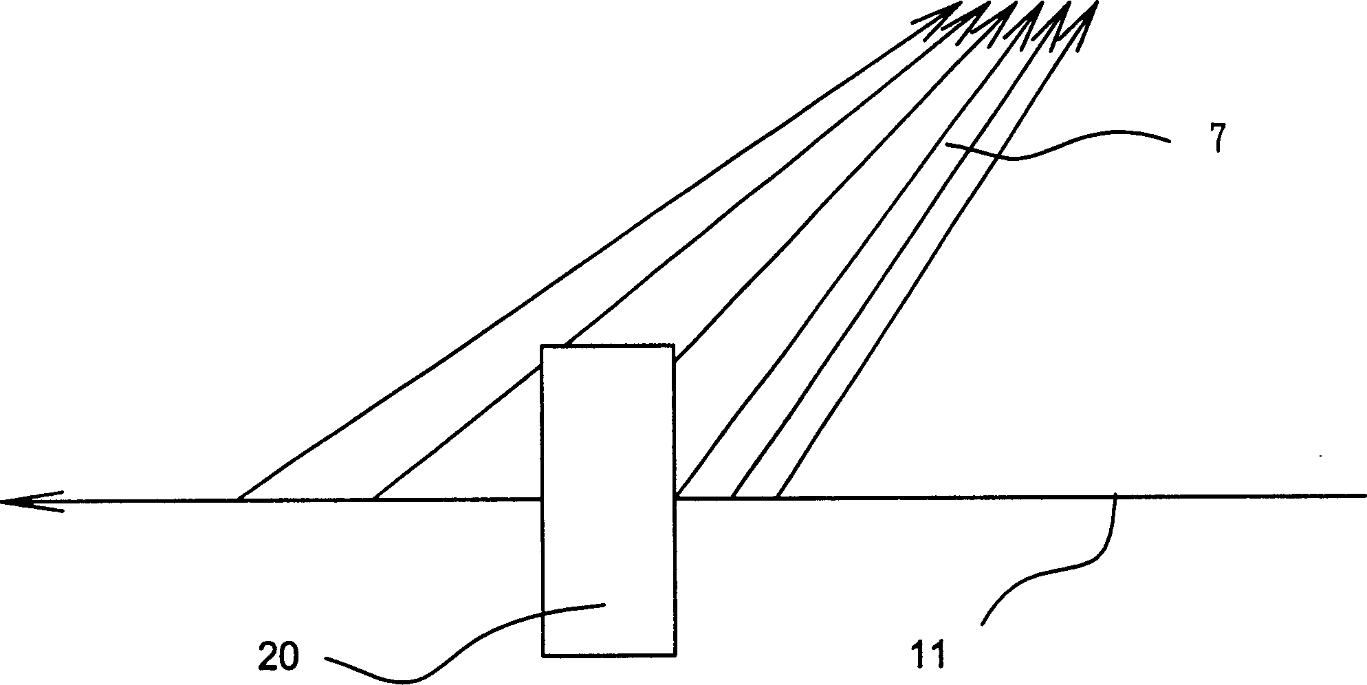
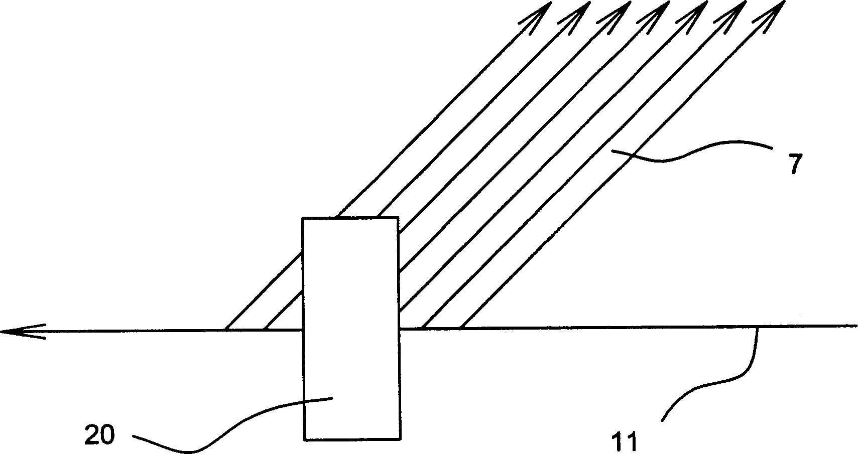
[0017] In order to improve the problem of uneven resolution in the direction of projected light in the prior art, the present invention provides a shape measuring device for biaxially modulating image magnification, adopting an optical system to provide a biaxially modulating image magnification The unique shape measurement device adopts the characteristics of the telecentric optical structure of the optical system to make the resolution of the far and near uniform.

[0018] Such as Figure 4 As shown, it is a perspective view of the shape measuring device of the present invention. A light source 10 is used to project a plane light (or line beam) onto the surface of an object 20, and the intersection line (or point) 21 with the surface of the object 20 can be calculated using the principle of triangulation distance measurement. its three-dimensional coordinates. Firstly, the light 21 is reflected to a curved mirror 40 and then reflected into a cylindrical lens group 50 , and ...

no. 2 example

[0020] Such as Image 6 As shown, it is another embodiment of the present invention, adopting a telecentric cylindrical lens group 40B (made up of a cylindrical lens 401B and a plane reflector 402B) to replace the curved reflector 40A; providing a light source 10 to form a projection light plane 11 to the object 20, intersecting on the object 20 as a point or line, from the optical path 30 through the cylindrical lens 42 and the plane reflector 40A, and then through the cylindrical lens group 50 (concave cylindrical lens 51, convex cylindrical lens 52) , is imaged on the CCD 62 by the imaging objective lens group 61 (lens). In order to allow the far and near resolution to be uniform, the focal length of the cylindrical lens 401B is close to the optical path distance between it and the imaging objective lens group 61 (lens), and the aperture is located on the imaging objective lens group 61, so that a telecentric optical framework is formed, and the optical coupling assembly 6...


PUM


Abstract

The shape measure has one light source to project to object to be measured, one electronic imaging device, such as one CCD camera, to take laser image, and one calculator to calculate the coordinate positions of various points. In the present invention, one curved reflector or one telecentric cylindrical lens combination is used in regulating the image scaling power in the laser projecting direction, and other cylindrical lens combination is used in regulating the image scaling power in the laser width direction to improve the resolution, which degrades with the increased distance during measurement. After precise optical analysis and design, the visible distance of CCD camera may become the effective measurement depth.

Description

technical field [0001] The invention relates to a shape measuring device for biaxially modulating the magnification of an image, which adopts the characteristics of a telecentric optical structure in an optical system to uniformize the resolution of the far and near, and is a high-resolution and uniform image-taking device. Background technique [0002] In the imaging device for general shape measurement, a fixed-focus lens is usually used to cooperate with a fixed-resolution and fixed-size CCD camera to have a fixed viewing angle in both vertical and horizontal directions, so when the distance from the object is closer, the range seen The smaller the distance, the greater the resolution; on the contrary, when the distance from the object is farther, the larger the range seen, the smaller the resolution. When the range of light (or surface) that the CCD camera can see in the direction of the projected light is larger than when it is perpendicular to the light (or surface), i...

Claims


Application Information

Patent Timeline
IPC IPC(8): G01B21/20
Inventor 林明慧胡杰
Owner IND TECH RES INST
Features
  • R&D
  • Intellectual Property
  • Life Sciences
  • Materials
  • Tech Scout
  • Unparalleled Data Quality
  • Higher Quality Content
  • 60% Fewer Hallucinations
Learn More