Eureka AIR delivers breakthrough ideas for toughest innovation challenges, trusted by R&D personnel around the world.

Continuous high gradient magnetic separator

A high-gradient magnetic separation and sorting technology, applied in the direction of high-gradient magnetic separators, can solve the problems of difficult separation of ultrafine particles and weak magnetic particles, high operation and maintenance costs, and difficult magnetic field switching operations.

Inactive Publication Date: 2003-09-17
INST OF PROCESS ENG CHINESE ACAD OF SCI
View PDF1 Cites 20 Cited by
  • Summary
  • Abstract
  • Description
  • Claims
  • Application Information

AI Technical Summary

Problems solved by technology

Its disadvantages are: the use of electromagnets cannot generate high magnetic field strength, and it is difficult to separate ultrafine particles and weak magnetic particles; intermittent operation has low separation efficiency
But its disadvantages are: the use of electromagnets cannot generate high magnetic field strength; the separation chamber cannot be sealed, and the separation operation of high temperature, high pressure and volatile liquids cannot be performed
[0007] 2. During the two alternate operations of capture and release in high-gradient magnetic separation, it is required that the background magnetic field acting on the magnetic medium separation chamber can be switched between application and removal. Although it is convenient for the electromagnet to realize this operation, it consumes a lot of power , the equipment structure is complex, it needs to be equipped with a cooling system, the operation and maintenance costs are high, especially the low magnetic field strength generated by the electromagnet has become the biggest disadvantage in its use
Permanent magnets can generate high magnetic field strength, have the advantages of reliable operation, low price, no need for auxiliary equipment, convenient operation and maintenance, and energy saving. They have been valued and developed, but the magnetic field switching operation is more difficult.
[0008] 3. The current high-gradient magnetic separation equipment is generally only suitable for the separation of magnetic particles under low temperature, low pressure and normal temperature and normal pressure conditions. These devices, such as the Chinese patent "Continuous high-gradient magnetic separation method for separating magnetic particles from fluid Device" Patent No. 99107814.4, "Continuous Separation Device for Ultrafine Magnetic Particles in Catalytic Hydrodesulfurization Device" Patent No. 01120631.4
However, it is difficult to separate magnetic particles under high temperature and high pressure conditions.

Method used

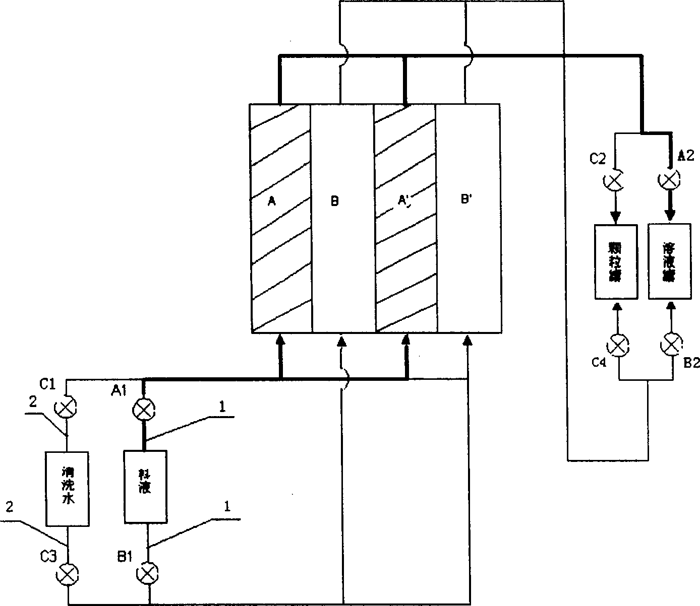

Image

  • Continuous high gradient magnetic separator
  • Continuous high gradient magnetic separator
  • Continuous high gradient magnetic separator

Examples


Embodiment Construction

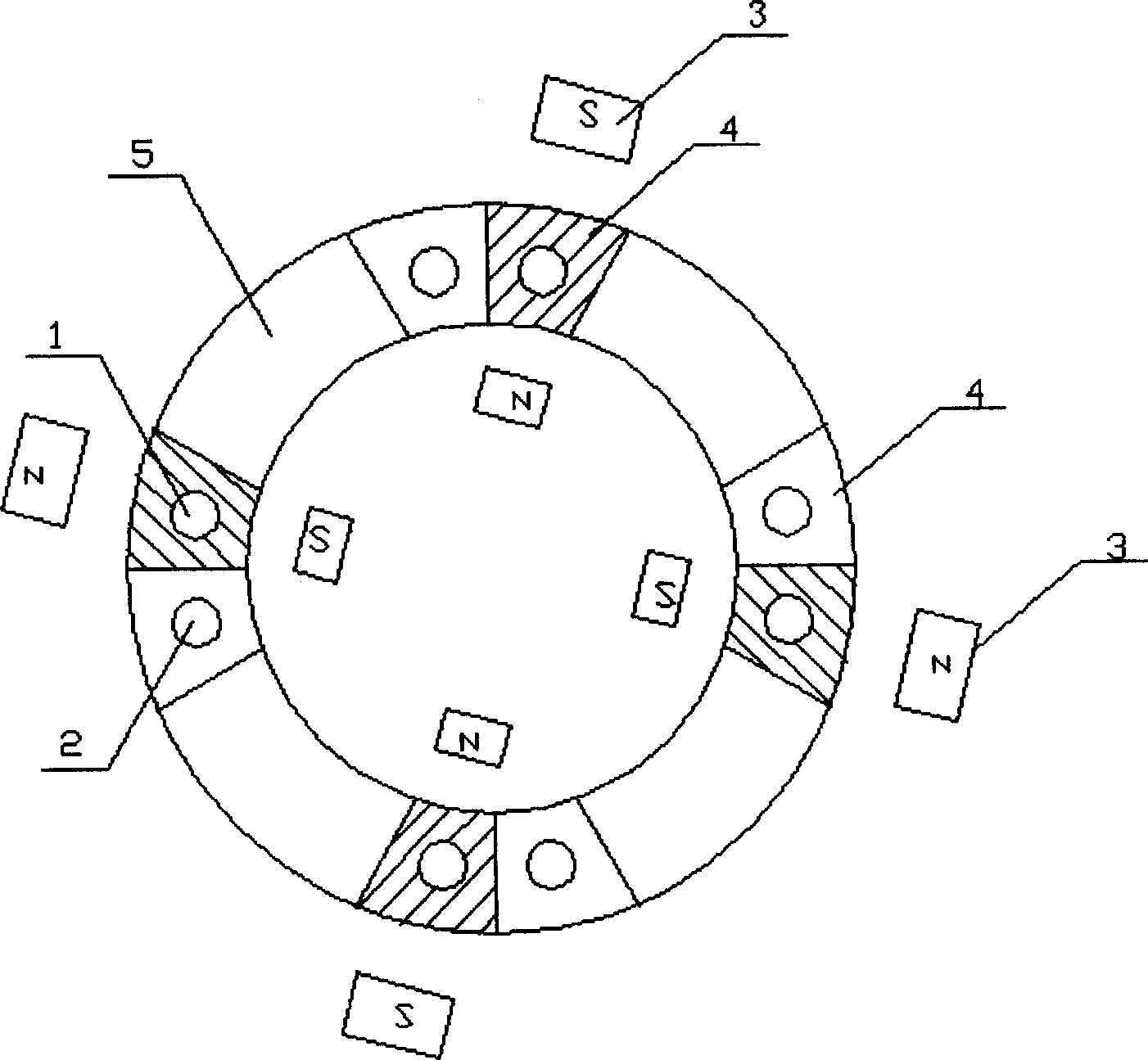
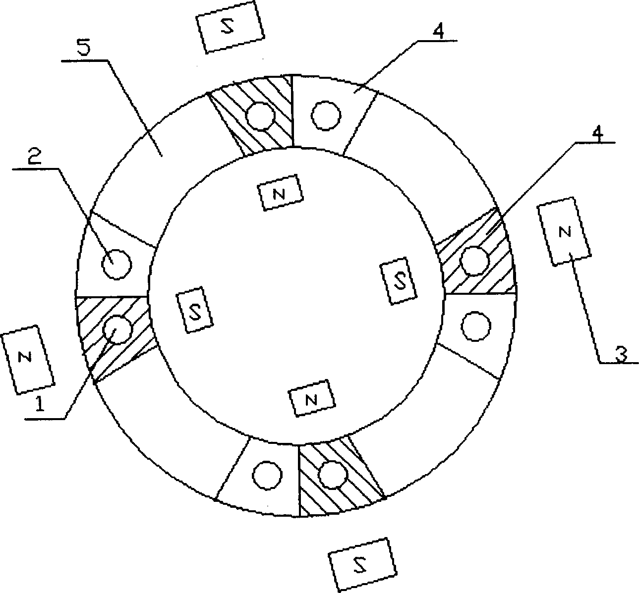
[0022] As shown in Figure 1 (a) and (b), a continuous high-gradient magnetic separator is composed of a plurality of separation chambers 4 connected to form a separation ring 5, and each separation chamber 4 is equipped with a feed pipe 1 and the cleaning water pipe 2, the feed pipe 1 and the cleaning water pipe 2 are all controlled by the electromagnetic valve described later. At least 4 pairs of C-shaped permanent magnets 3 are arranged around the sorting ring 5, and the magnetic field of the permanent magnets 3 is 600-4600 Oersted. The sorting chamber 4 is both a capture chamber and a flushing chamber in different operating periods, and the permanent magnet 3 periodically moves between the sorting chamber 4 (capture chamber and flushing chamber) to realize switching of the magnetic field while keeping the sorting chamber 4 stationary .

[0023] The sorting chamber 4 is in a sealed state, and is suitable for the separation of weakly magnetic tiny magnetic particles under hi...


PUM


Abstract

A high-gradient continuous magnetic separator for weakly magnetic small particles, has a separation ring composed of multiple separation chambers containing steel fibres and magnetic medium, and at least 4 pairs of C-shaped permanent magnets surrounding said separation ring. The said separation chamber has feed tube and washing water tube. Its advantages are simple structure and easy operation.

Description

technical field [0001] The invention relates to a continuous magnetic separation device, which is suitable for the separation of tiny particles under normal temperature and normal pressure conditions, and more suitable for high temperature and high pressure conditions and weak magnetic properties. Background technique [0002] Magnetic separation technology is not only widely used in the sewage treatment of mineral processing, steel mills and power plants, but also for the selective separation of particle systems in the coal industry, non-metallic industry, atomic energy industry, chemical industry, and especially in biotechnology. effective solution. In the process of biochemical separation, magnetic separation technology has many potential advantages compared with other separation technologies, and it is an important development direction of biochemical separation. [0003] When the magnetic particles are micron-sized or larger, the magnetic separation operation does not ...

Claims


Application Information

Patent Timeline
IPC IPC(8): B03C1/025
Inventor 马志亚刘会洲安振涛陈家镛
Owner INST OF PROCESS ENG CHINESE ACAD OF SCI
Why Eureka
Eureka Blog
Learn More