
Drying equipment for filature

A technology of drying device and dryer, which is applied in the directions of silk reeling, drying solid materials, and heating to dry solid materials, etc. It can solve the problems of non-compliance between water content of silk flakes and process standards, poor drying quality of silk flakes, and large differences in drying degree, etc. problems, to achieve the effect of maintaining the health of workers, saving operating costs, and reducing operating costs

Inactive Publication Date: 2003-10-08
SICHUAN UNIV TIANYOU BIOLOGIC ENG
View PDF0 Cites 4 Cited by
  • Summary
  • Abstract
  • Description
  • Claims
  • Application Information

AI Technical Summary

Problems solved by technology

Even China, the largest silk country, India, the second largest silk country, and Japan, Brazil, Uzbekistan, Vietnam, Thailand and other major silk producing countries have not broken through the above-mentioned technological framework. Efforts have been made in dust removal and large-scale heat dissipation. Although some progress has been made in saving coal and reducing smoke and dust, it has not been able to fundamentally solve the problems of low thermal efficiency, serious soot and coal pollution, poor drying quality of silk flakes, and drying Frequently Asked Questions
[0003] Coal heating silk flake drying process is heat transfer in an open diffuse intermediate medium, air convection heating is the main form, and the heating object is silk flakes. Between the sheet and the silk sheet, the dryness of the outer, middle, and inner layers of the same sheet varies greatly, and most of the heat is used for non-heating objects such as pipe networks, carriages, frames, and workshops, causing "heat pollution" and forcing Workers working in high temperature

Method used


Image

  • Drying equipment for filature
  • Drying equipment for filature
  • Drying equipment for filature

Examples


Embodiment Construction

[0021] Below in conjunction with accompanying drawing, the present invention is described in further detail:

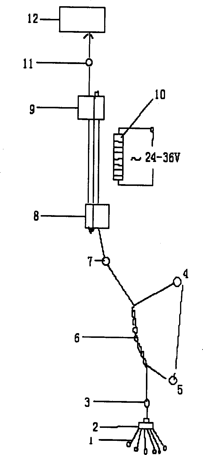
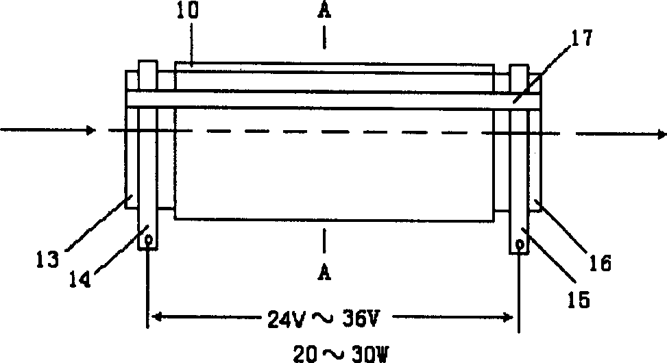
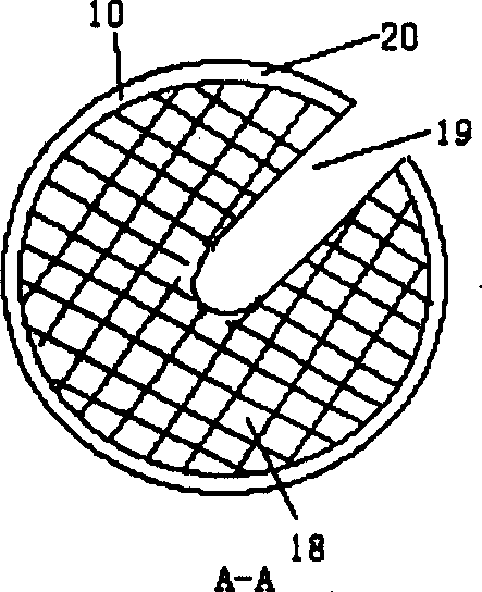
[0022] according to figure 1 , figure 2 , image 3 It is known that the thread heads of several Zhengxu cocoons 1 are wound and adhered by the thread splicer 2 to form a thread group, and the thread group rises through the thread splicer, and then passes through the thread splicer 3 to gather into filaments, The thread is inserted into the upper and lower drums 4, 5 and then twisted to form a sheath 6. The thread continues to rise and is placed on the upper and lower multi-groove pulleys 9 and 8 of the thread drying device after being positioned by the guide wire hook 7. The thread is in between. Heated by the thread drier 10 during several times of orbital movement, when the moisture regain dropped to 13-16%, the thread rose and passed through the intertwining guide wire hook 11 of the winding device to continue the post-processing. According to the formation and...


PUM


Abstract

A drier for reeling silk has winding unit and silk-guiding hooks for locating. The upper and lower multi-groove pulleys are respectively connected to the silk-guiding hooks for winding and locating. A PTC drier arranged at side of said pulleys has the coated far infrared layer in the thermosensitive semiconductor ceramic channel and the joint clamps at both ends. Its advantages are sipmle structure high drying quality and high thermal efficiency up to 50-55%.

Description

technical field [0001] The invention relates to the technical field of silk production in the silk industry, and more specifically relates to a silk reeling drying device. Background technique [0002] Although there are more than 60 countries in the world that produce silk, with an annual output of 70,000 to 80,000 tons of silk in recent years, the heating process of cocoon reeling in various countries has been using coal-fired boilers to generate steam and transport it through pipelines. The steam pipe network heats the air and air convection A method of heating the filament. So far, the reform of coal-burning heating technology is basically a local improvement without changing the energy type and heating process. Even China, the largest silk country, India, the second largest silk country, and Japan, Brazil, Uzbekistan, Vietnam, Thailand and other major silk producing countries have not broken through the above-mentioned technological framework. Ef...

Claims


Application Information

Patent Timeline
IPC IPC(8): D01B7/04F26B3/30
Inventor 赵力宾谭之虎邹方清刘辉芬
Owner SICHUAN UNIV TIANYOU BIOLOGIC ENG
Learn More