Gas turbine generating system and flow by cooling liquefied natural gas to separate carbon dioxide

A liquefied natural gas and carbon dioxide technology, applied in gas turbine installations, machines/engines, mechanical equipment, etc., can solve problems such as system efficiency decline, insufficient LNG cold utilization, consumption, etc. System simple effect

Inactive Publication Date: 2003-10-08
南京中科众能科技有限公司
View PDF0 Cites 47 Cited by
  • Summary
  • Abstract
  • Description
  • Claims
  • Application Information

AI Technical Summary

Problems solved by technology

But this way is cold to LNG Insufficient utilization, generally less than 1% improvement in combined cycle efficiency
[0018] Whether in the conversion of fuels or the separation of CO from flue gases after combustion 2 , will consume extra energy and reduce the efficiency of the system
At the current state of the art, the separation of CO 2 Reduce system efficiency by 5 to 10 percent

Method used


Image

  • Gas turbine generating system and flow by cooling liquefied natural gas to separate carbon dioxide
  • Gas turbine generating system and flow by cooling liquefied natural gas to separate carbon dioxide
  • Gas turbine generating system and flow by cooling liquefied natural gas to separate carbon dioxide

Examples


Embodiment Construction

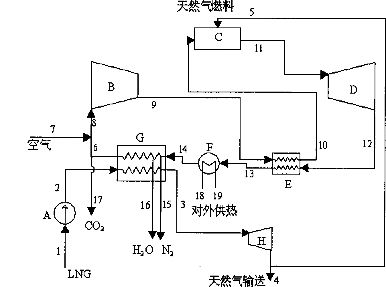
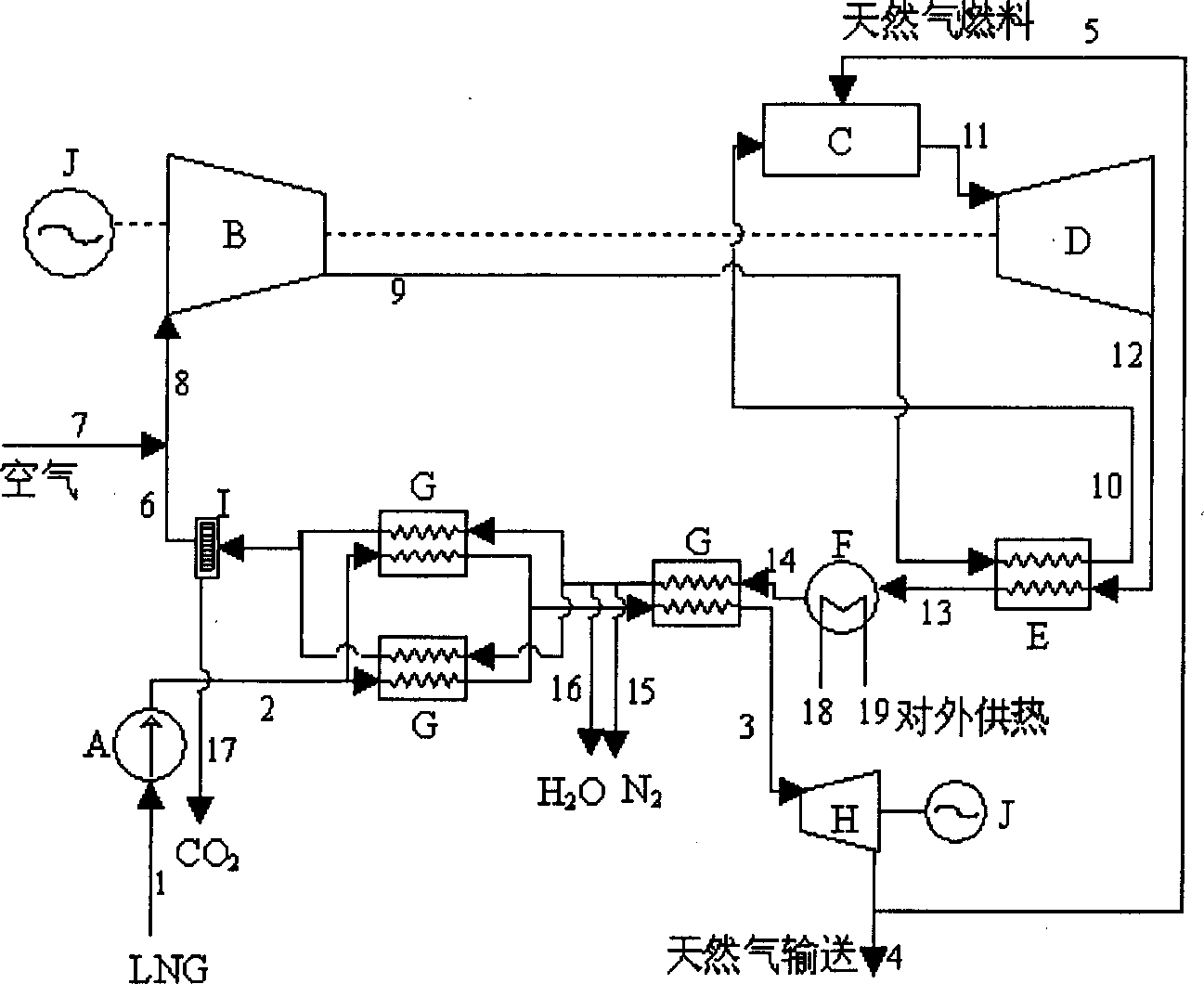
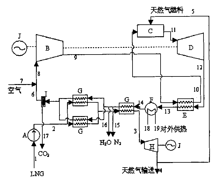
[0063] Please see figure 1 and figure 2 , the main parts of the present invention are semi-closed, regenerative gas turbine circulation system and LNG gasification system, in this system: A-LNG booster pump; B-compressor; C-combustion chamber; D-gas turbine; E -regenerator; F-heating network heater; G-LNG vaporizer; H-natural gas expansion turbine; I-filter; J-generator.

[0064] The connection in the above system is a known technology, and the present invention will not be described in detail here.

[0065] System process description:

[0066] LNG is compressed to state 2 through booster pump A (this process is unnecessary when LNG has sufficient pressure); in LNG vaporizer G, LNG is heated to become superheated natural gas 3; and then reaches low pressure through expansion turbine H , Normal temperature state 4 / 5 (there is expansion turbine when the natural gas delivery pressure is subcritical pressure); then part of the natural gas 5 enters the combustion chamber C of t...


PUM


Abstract

A gas turbine generating system and its process of separating CO2 with LNG is to compress ING by booster pump to be heated and gasified in LNG gasifier to charge to cold natural gas by expansion turbine, a part enters into the gas turbine combustion chamber as fuel and the rest most part is transported to outside users. Cold N mixed with air enters into a compressor, to be heated in a reheater then enters into a combustion chamber to generate burning reaction with natural gas to generate high temp gas to enter into the turbine expansion. Turbine exhaust is cooled in the reheater, and cooled by hot net heater and cooled further in LNG gasifier and remained N is expelled about environment temp, condensed water is recovered to solid CO2.

Description

[0001] Gas turbine power generation system and process for separating carbon dioxide technical field [0002] The invention relates to a cooling system for liquefied natural gas (LNG) Using power generation technology and separating carbon dioxide (CO 2 ) technology combined power generation system and its process. Background technique [0003] The technology related to the present invention mainly includes LNG refrigeration Using power generation technology and CO 2 Separation technologies, the development status and system characteristics of their respective technologies are as follows. [0004] 1. LNG cold Utilize power generation technology [0005] LNG is a relatively safe and clean energy. Since the sulfur component is precipitated and separated in solid form during the cryogenic process of natural gas liquefaction, LNG does not contain sulfide. The natural gas liquefaction process requires a lot of compression work. The volume of liquefied natural gas (LNG...

Claims


Application Information

Patent Timeline
Patent Type & Authority Applications(China)
IPC IPC(8): F02C3/20F02C6/00
CPCY02E20/16Y02E20/14
Inventor 邓世敏金红光蔡睿贤
Owner 南京中科众能科技有限公司
Why Eureka
Try Eureka