Self-injection locking fibre-optical laser circulator

A self-injection locking, fiber laser technology, applied in the field of optical gyroscope, to achieve the effect of large dynamic range, light weight, and beneficial to measurement accuracy

Inactive Publication Date: 2003-10-15
UNIV OF SCI & TECH OF CHINA
View PDF1 Cites 13 Cited by
  • Summary
  • Abstract
  • Description
  • Claims
  • Application Information

AI Technical Summary

Problems solved by technology

[0004] The purpose of the present invention is to provide a new optical gyroscope, that is, self-injection locking fiber laser gyroscope, which can not only solve

Method used


Image

  • Self-injection locking fibre-optical laser circulator
  • Self-injection locking fibre-optical laser circulator

Examples


Embodiment Construction

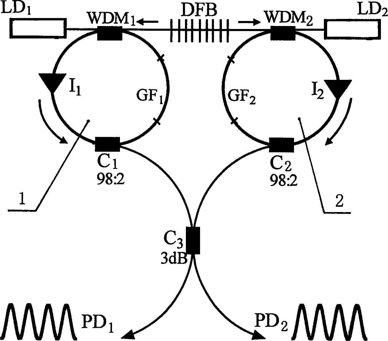
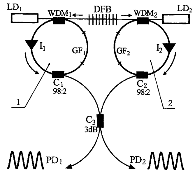
[0033] Embodiments of the present invention will be described below in conjunction with the accompanying drawings. It can be seen from the figure that the semiconductor laser LD is a pump laser usually used in an erbium-doped fiber amplifier, the model is QLM9S470-915, the working wavelength is 980nm, and the output power is 150mW; the DFB is a single-frequency fiber laser doped with erbium. The bidirectional output power is 0.25mW, the wavelength is 1.546μm, and the line width is 2MHz; the length of the two optical fiber ring cavities is about 4m, and the distance between the longitudinal modes is about 50MHz. Optical fiber, the gain is 15dB / m; the isolator adopts CASIX products (A grade), the return loss is 65dB, and the peak isolation is 42dB; the coupler C 1 and C 2 The coupling ratio is 98:2, of which 2% is drawn from the cavity as the detection signal, C 3 The coupling ratio of the laser is 1:1 (ie 3dB) so that the two lasers interfere with each other; the WDM of the w...


PUM


Abstract

The present invention relates to optical gyro, and is especially fiber laser gyro comprising fiber laser, detector and differential frequency processing circuit. It features that the fiber laser consists of semiconductor laser with tail fiber, single-frequency distributed feedback fiber laser DFB, fiber ring and fiber coupler, with the fiber ring comprising wavelength division multiplexer, isolator, gain fiber and fiber coupler. Two fiber rings with gain fiber forms two independent resonant cavities, into which the DFB injects seed laser to lock their work wavelength. The isolator makes the laser work in single-direction traveling wave state, and the laser transmission direction is clockwise in one ring and counterclockwise in the other. The present invention eliminates spatial hole burning in homogeneously expanded gain medium and interlock effect caused by back scattering, and makes laser in two ring cavities work in narrow-line width single-longitudinal mode state.

Description

Technical field: [0001] The invention relates to an optical gyroscope, in particular to a fiber laser gyroscope. Background technique: [0002] As an important sensor, the gyroscope has important applications in military and civilian applications such as positioning, orientation, and navigation of satellites, aircraft, ships, and automobiles. A new generation of optical gyroscopes based on the Sagnac effect (such as laser gyroscopes, interferometric fiber optic gyroscopes, etc.) has attracted people's research interest. As the first generation of products, the laser gyroscope has entered practical application in the field of medium and low precision. It adopts the difference frequency signal detection method, the electronic processing is more convenient, and the signal processing accuracy is higher; but the discrete optical components and defects such as short life, large volume, and heavy weight affect the application of laser gyroscopes in high-precision fields. As the s...

Claims


Application Information

Patent Timeline
IPC IPC(8): G01C19/66
Inventor 许立新明海谢建平王安廷黄文财吴云霞
Owner UNIV OF SCI & TECH OF CHINA
Why Eureka
Try Eureka