Parabolic reflector lamp assembly capable of reduced lamp seal temp.

A technology of reflector and reflective layer, applied in the field of reflector lamps and electric lamps enclosed in reflectors

Inactive Publication Date: 2003-10-22
OSRAM SYLVANIA INC
View PDF1 Cites 3 Cited by
  • Summary
  • Abstract
  • Description
  • Claims
  • Application Information

AI Technical Summary

Problems solved by technology

[0006] Unfortunately, lifetime testing has shown that HCI lamps installed in existing lamp structures fail prematurely at approximately 1500-2000 hours instead of the rated 10,000 hours

Method used


Image

  • Parabolic reflector lamp assembly capable of reduced lamp seal temp.
  • Parabolic reflector lamp assembly capable of reduced lamp seal temp.
  • Parabolic reflector lamp assembly capable of reduced lamp seal temp.

Examples


Embodiment Construction

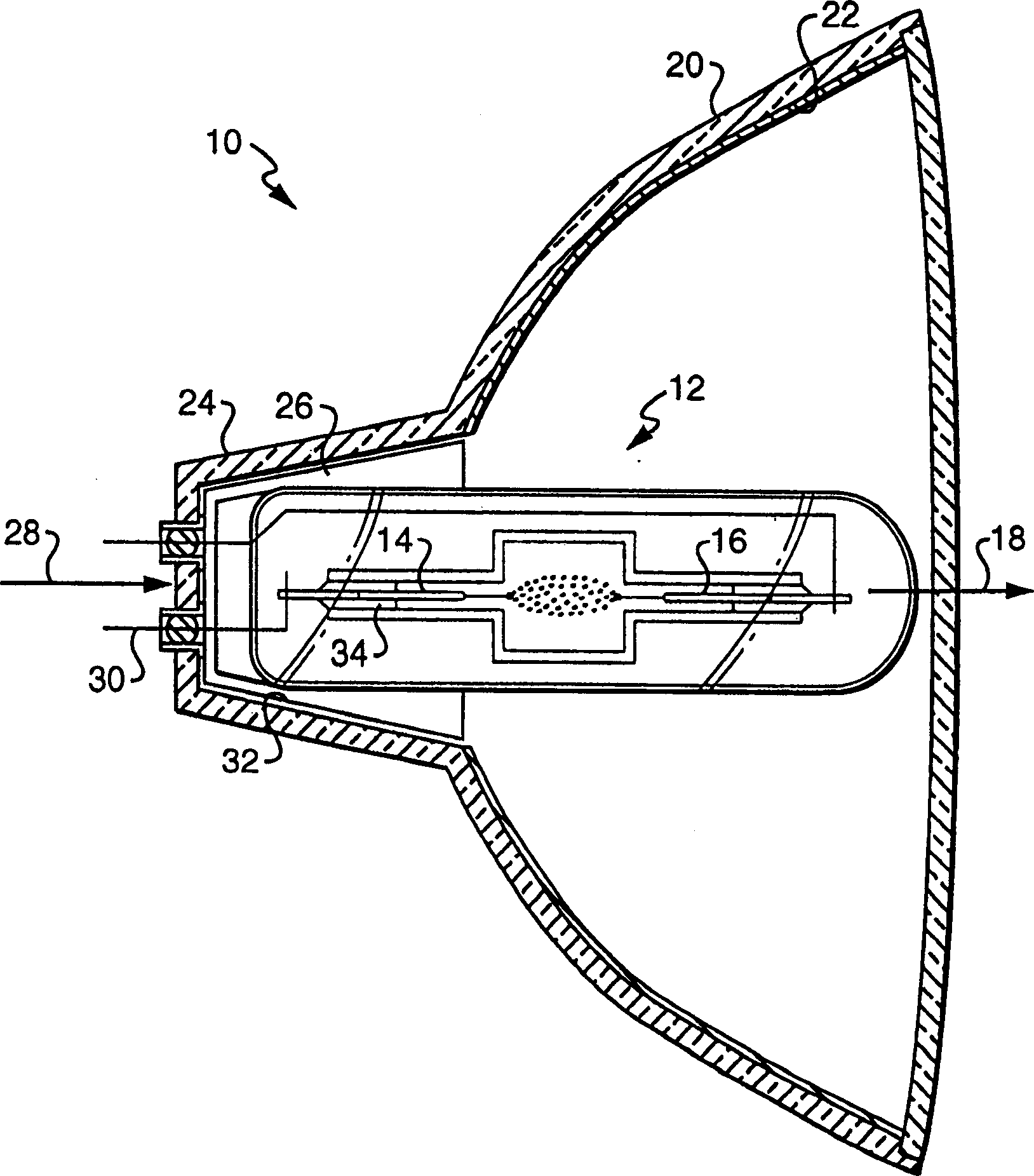
[0011] figure 1 A schematic cross-sectional view of a preferred embodiment of a lamp assembly with an internal light absorbing coating is shown. A preferred PAR lamp assembly 10 includes a light source 12 having two sealed electrodes 14 , 16 defining a lamp axis 18 ; a concave ceramic envelope 20 having an internal reflective surface 22 . The housing 20 also has a neck 24 defining a neck cavity 26 and a reflector axis 28 . The neck 24 is provided with electrical connections 30 and mechanical support for the light source 12 . Housing 20 surrounds light source 12 to reflect light from light source 12 to the area to be illuminated during operation of the lamp. Preferably the light source 12 and reflector 20 are oriented such that the lamp axis 18 is substantially coaxial with the reflector axis 28, and at least a portion of at least one of the electrodes 14, 16 extends in the neck cavity 26, and an area With a substantially non-transmissive light-absorbing layer 32 .

[0012]...


PUM


Abstract

The neck of a typical PAR lamp tends to focus the light issued in the neck or heel of the lamp back onto the lamp seals. The focused lost light then tends to overheat the seal and shorten lamp life. A practical solution is to intercept this lost light with a light absorbing layer. The light is then converted to heat in the layer. The heat is then re-radiated in an unfocused fashion with only a small portion of it redirected to the seal area. The interception layer may be formed as a black top coating on the neck interior or the neck exterior if the reflector is otherwise light transmissive. Alternatively, the neck may be formed from a translucent or opaque material that then converts the light into heat in the body of the reflector wall. The neck is then specifically not metallized so as to reflect light from the internal neck surface back to the lamp seal.

Description

technical field [0001] The present invention relates to electric lamps, and in particular to electric lamps enclosed in reflectors. More particularly, the present invention relates to a reflector lamp (PAR) having a ceramic metal halide lamp envelope with reduced lamp envelope seal temperature. Background technique [0002] A new class of metal halide lamps has been developed in ceramic lamp envelopes with novel metal halide seals (Geven et al., US 5,424,609; and Carleton et al., J.III.Eng.Soc.P139-145 , Winter 1996 (Proc. Of IESNA Annual Conference)). These lamps include a fill chemistry of metal halide and two electrodes. A high voltage pulse between the electrodes is used to light the lamp. Normal current and voltage are then applied through the electrodes to energize the enclosed gas and fill material into a plasma state. In addition to an inert starting gas such as argon or xenon, typical fillers include rare earth halides and various other additives, including thal...

Claims


Application Information

Patent Timeline
Patent Type & Authority Applications(China)
IPC IPC(8): F21S2/00F21V7/00F21V7/06F21V7/22F21Y101/00H01J13/32H01J61/18H01J61/34H01J61/35H01J61/52H01J61/82H01J61/86H01K1/26
CPCH01J61/34H01J61/35H01J61/125H01J61/523H01J61/827H01J61/30
Inventor W·P·拉帕托维奇R·A·斯内尔格罗维
Owner OSRAM SYLVANIA INC
Why Eureka
Try Eureka