Bistable electromagnetic microdriver and mfg. method thereof

A micro-driver and bistable technology, applied in relays, piezoelectric/electrostrictive/magnetostrictive devices, non-polar relays, etc., can solve the problems of low efficiency of electromagnetic action, difficulty in reducing the quality of moving parts, and restrictions on motion response speed, etc. question

Inactive Publication Date: 2003-10-29
SHANGHAI JIAO TONG UNIV
View PDF0 Cites 20 Cited by
  • Summary
  • Abstract
  • Description
  • Claims
  • Application Information

AI Technical Summary

Problems solved by technology

However, the constant magnetic force used for attitude maintenance in this design is not the electromagnetic force generated by the usual closed magnetic flux at the air gap, but the torque of the soft magnetic cantilever beam being magnetized in the magnetic field. The efficiency of electromagnetic action is low, and the torque and The size of the cantilever beam is directly proportional, which will make it difficult to reduce the quality of the moving parts and restrict the speed of motion response
In addition, the back-mounted permanent magnet structure is not conducive to integrated manufacturing

Method used


Image

  • Bistable electromagnetic microdriver and mfg. method thereof
  • Bistable electromagnetic microdriver and mfg. method thereof
  • Bistable electromagnetic microdriver and mfg. method thereof

Examples


Embodiment Construction

[0022] The technical solutions of the present invention will be further described below in conjunction with the accompanying drawings and specific design embodiments.

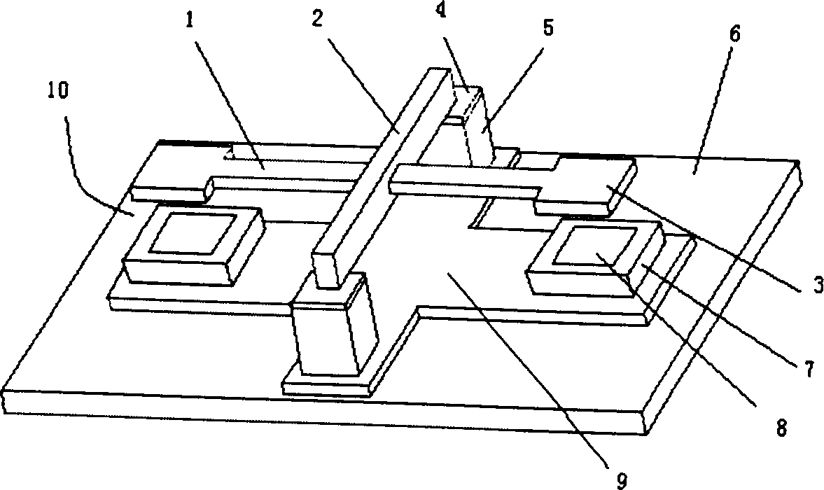
[0023] figure 1It is a schematic three-dimensional structure diagram of a typical design representing the main technical features of the present invention. It should be pointed out that the size ratio of each part in the figure does not necessarily conform to the optimal structural size of the present invention, but only shows the mutual positional relationship of each part.

[0024] refer to figure 1 As shown, the bistable micro-actuator of the present invention is based on the soft magnetic substrate 9 distributed on the substrate 6, and a pair of permanent magnet bases 5 are arranged symmetrically on both sides; the soft magnetic torsion beam 2 passes through the soft magnetic transition layer 4 is placed on a pair of bases 5 to form a bridge structure; a set of planar windings 7 are respectively arranged o...


PUM


Abstract

A bistable electromagnetic microdriver is structurally characterized by that a pair of permanent-magnet bases are symmetrically arranged on a soft-magnetic liner on base, a soft-magnetic torsional beams is arranged via soft-magnetic transition layer on said two bases to form a bridge structure, and a pair of soft-magnetic cantilevers are horizontally and symmetrically extended from the middle part of torsional beam to make their ends above the planar windings containing iron core on said liner. An air gap is between the end of cantilever and planar winding.

Description

Technical field: [0001] The invention relates to a bistable electromagnetic micro-driver and a preparation method thereof, which is an electromagnetic micro-driver and an integrated manufacturing method thereof which realizes displacement drive through the electromagnetic effect of windings and maintains attitude without power consumption by means of permanent magnets. Driven switching devices are related to automatic control or micro-electromechanical systems [0002] technology field. Background technique: [0003] Micro-electromechanical systems and related technologies push the size of optical, mechanical, and electrical functional devices closer to the size of microelectronic devices, endowing them with the opportunity and possibility of integrated manufacturing and functional compounding, which can not only significantly improve the existing The efficacy and competitiveness of the product, and the possibility of creating a new structural form, have attracted much atte...

Claims


Application Information

Patent Timeline
Patent Type & Authority Applications(China)
IPC IPC(8): B81B3/00B81C1/00H01H49/00H01H51/01
Inventor 丁桂甫张永华赵小林杨春生蔡炳初
Owner SHANGHAI JIAO TONG UNIV
Why Eureka
Try Eureka