Desending catalytic cracking reactor and its application

A catalytic cracking and reactor technology, applied in catalytic cracking, cracking, petroleum industry, etc., can solve the problems of equipment coking, insufficient heavy oil conversion capacity, low oil contact efficiency, etc., to reduce pulsation and back mixing, and strengthen heavy oil conversion Ability, the effect of preventing serious coking

Inactive Publication Date: 2003-11-05
CHINA PETROLEUM & CHEM CORP +1
View PDF3 Cites 9 Cited by
  • Summary
  • Abstract
  • Description
  • Claims
  • Application Information

AI Technical Summary

Problems solved by technology

[0007] To sum up, a series of problems such as low oil agent contact efficiency, insufficient heavy oil conversion capacity, and equipment coking generally exist in the prior art.
Up to now, there is no report on a down-flow reactor that can properly solve the above problems and have good reaction performance.

Method used


Image

  • Desending catalytic cracking reactor and its application
  • Desending catalytic cracking reactor and its application
  • Desending catalytic cracking reactor and its application

Examples


Embodiment 1

[0041] This example illustrates that the product distribution and product properties can be significantly improved by adopting the descending reactor provided by the present invention.

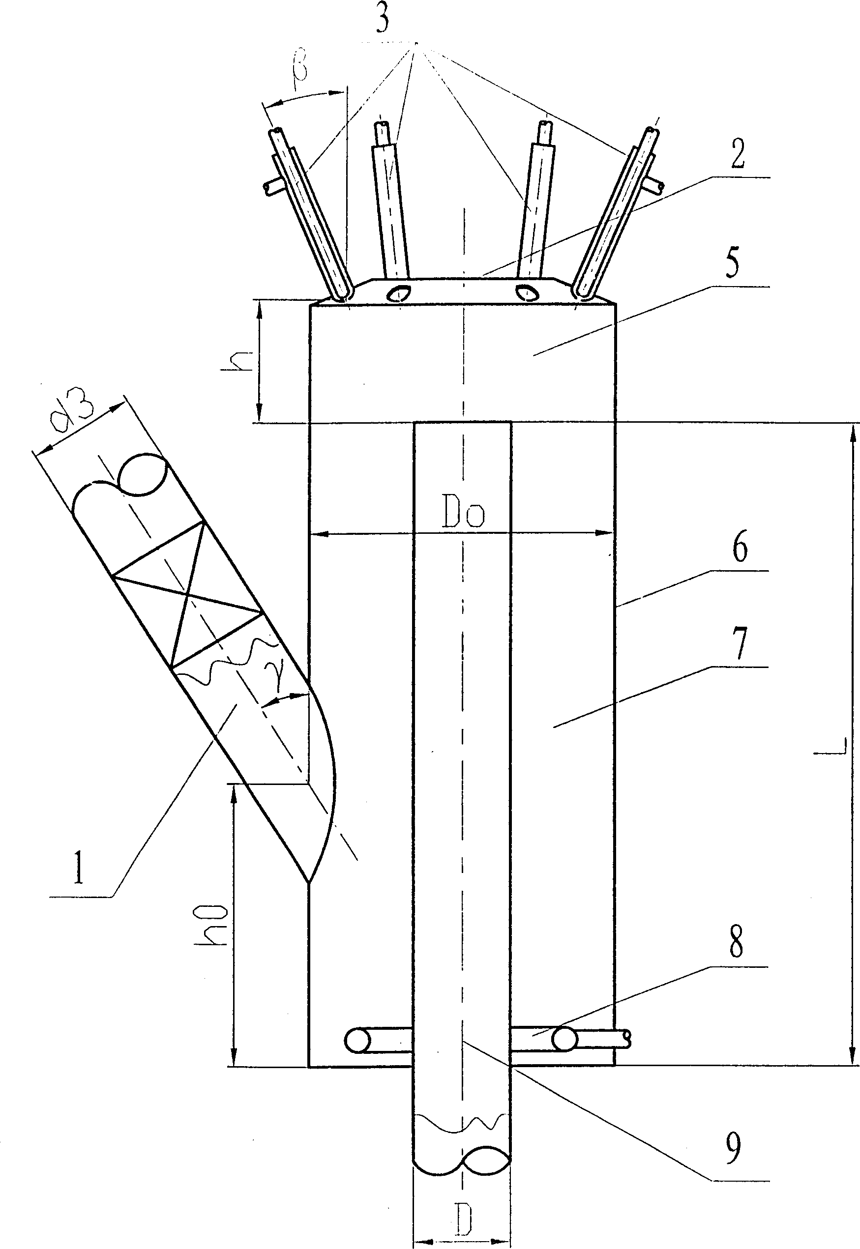
[0042] The principle flow chart of the catalytic cracking medium-sized unit used in the test Figure 11 , the structural diagram of the down-flow reactor is shown in figure 1 . The diameter of the descending reaction tube D=20mm; the diameter of the outer cylinder Do=2.5D; the height difference L=6D between the inlet of the descending pipe and the bottom of the outer cylinder; the number of nozzles is 4; the angle between each nozzle and the vertical direction β=30°, the height difference h=1.25D from the outlet of the nozzle to the inlet of the down pipe; the diameter of the catalyst delivery pipeline d3=0.8D, the angle between the center line and the vertical direction γ=30°, the catalyst delivery pipe and the outer The height difference h0=3D from the intersection point of the cylinder t...

Embodiment 2

[0045] This example illustrates that the product distribution and product properties can be significantly improved by adopting the descending reactor provided by the present invention.

[0046] The principle flow chart of the catalytic cracking medium-sized unit used in the test Figure 12 , the structural diagram of the down-flow reactor is shown in Figure 10 . The diameter of the downcomer reactor is D=20mm; the cone angle of the outer cylinder is β0=22.5°, and the diameter of the lower opening is Db=2D; the height difference from the upper edge of the inlet structure of the downcomer to the bottom of the outer cylinder is L=6D ; The number of nozzles is 4; the angle β=45° between each nozzle and the vertical direction, the height difference h=1.35D from the exit of the nozzle to the upper edge of the down pipe narrowing section; the diameter of the cone bottom of the diversion cone Dt= 3D, its cone angle =100°, the height difference h1=0.5D from the upper edge of the do...


PUM

PropertyMeasurementUnit
angleaaaaaaaaaa
angleaaaaaaaaaa
diameteraaaaaaaaaa

Abstract

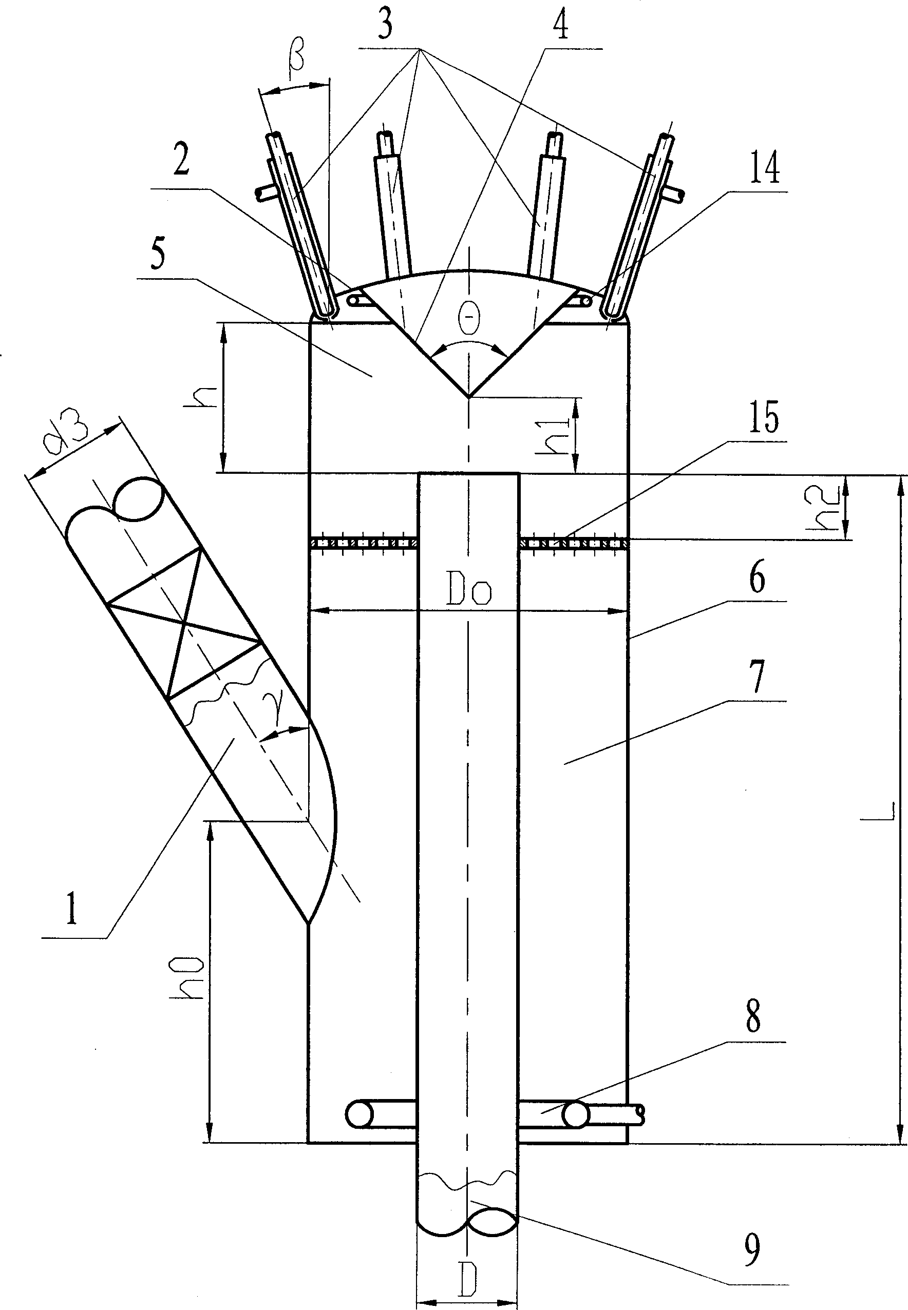
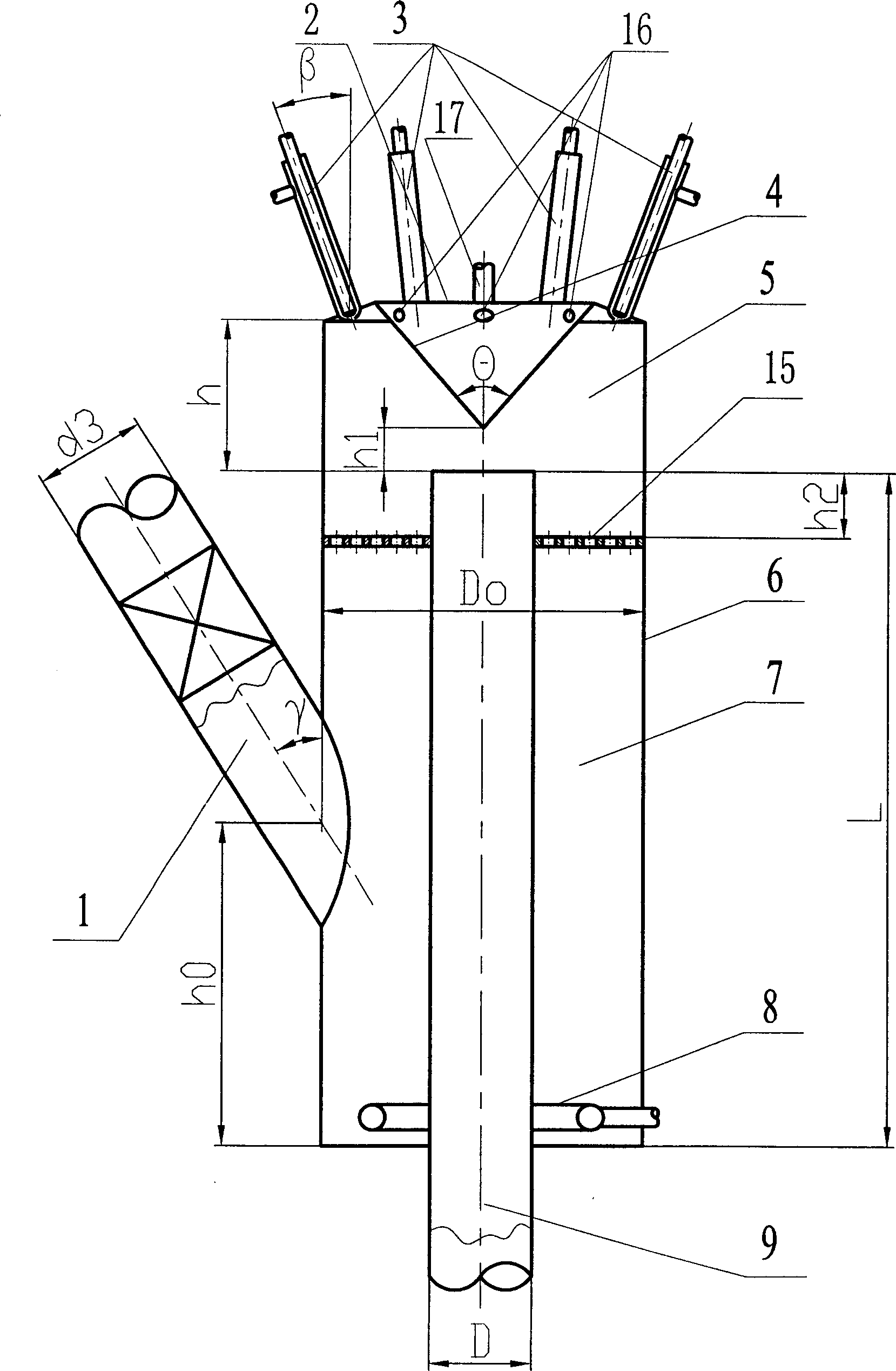
The descending catalytic cracking reactor includes the members of: catalyst conveying pipe, reactor top cover, material nozzle, outer reactor cylinder, medium pre-lifting distributor and descending reaction pipe. The descending reaction pipe and the outer reactor cylinder are set vertically and coaxially; the upper end of the outer reactor cylinder is connected to the top hermetically to constitute the cavity over the inlet of the descending reaction pipe as the material atomizing chamber, the outer reactor cylinder has its bottom connected hermetically to the outer wall of the descending reaction pipe; the upper section of the descending reaction pipe is inside the outer reactor cylinder while the lower section extends beyond the bottom of the cylinder; the material nozzle is set on thetop cover; the catalyst conveying pipe is connected to the outer cylinder and communicated to the catalyst pre-lifting area; and the medium pre-lifting distributor is set in the bottom of the catalyst pre-lifting area.

Description

technical field [0001] The invention belongs to catalytic cracking equipment for petroleum hydrocarbons in the absence of hydrogen, more specifically, a descending catalytic cracking reactor and its application. Background technique [0002] Catalytic cracking has developed rapidly since its industrialization in 1936, and it has become the most important process in the secondary processing of crude oil. Over the years, through unremitting research and exploration by refiners, considerable progress has been made in catalytic cracking technology and engineering. [0003] USP4514285 discloses a catalytic cracking reaction system for regeneration of downcomer and dilute phase riser. After the catalyst is regenerated through the dilute-phase riser, the flue gas is removed in the regeneration degassing tank, the catalyst density is increased, and after forming a dense-phase bed, it enters the downlink reaction tube through the catalyst distribution plate, and the raw oil passes t...

Claims


Application Information

Patent Timeline
Patent Type & Authority Applications(China)
IPC IPC(8): C10G11/00
Inventor 许克家侯栓弟钟孝湘张久顺张执刚张瑞驰李松年朱丙田
Owner CHINA PETROLEUM & CHEM CORP
Why Eureka
Try Eureka