Surge protective method by self-control surge current triggered gap discharge

A technology of triggering gap and main discharge gap, applied in emergency protection circuit devices, electrical components, circuit devices, etc. for limiting overcurrent/overvoltage, which can solve the problems of large inter-electrode capacitance, low precision, short-circuit effect, etc. , to achieve the effect of large surge current capacity, low residual voltage parameters, and short response time

Inactive Publication Date: 2003-11-19
黄兴英
View PDF1 Cites 8 Cited by
  • Summary
  • Abstract
  • Description
  • Claims
  • Application Information

AI Technical Summary

Problems solved by technology

[0007] Disadvantages: a. Slow response time (greater than 100ns to ms level); b. Harmful follower current; c. Performance parameters are easily affected by the environment; d. Short life; e. Large inter-electrode capacitance
[0010] Disadvantages: a. The residual voltage is relatively high; b. The use exceeding the rated current capacity may cause an explosion; c. The inter-electrode capacitance value is large, which is not suitable for lightning protection of high-frequency lines; d. There is leakage current, which is easy to Ageing;
[0013] Disadvantages: a. Small flow rate (hundreds of amperes); b. Short circuit effect when damaged
Its advantages: it can have a large flow capacity; its disadvantages: according to the introduction, the response time can reach more than 100ns; the trigger ignition voltage is too high, and it is not easy to control, the precision is low, and the residual voltage value is high; the gap distance is small, and it is easy to produce harmful Follow the current; the ignition voltage above several thousand volts cannot be applied to the protection of precise signal lines and antenna feeder lines at all; due to the limitation of trigger materials, it is also difficult to apply to high voltages above several thousand volts or even tens of thousands or hundreds of thousands of volts line

Method used


Image

  • Surge protective method by self-control surge current triggered gap discharge
  • Surge protective method by self-control surge current triggered gap discharge
  • Surge protective method by self-control surge current triggered gap discharge

Examples


Embodiment Construction

[0034] Below in conjunction with accompanying drawing, the present invention will be further described.

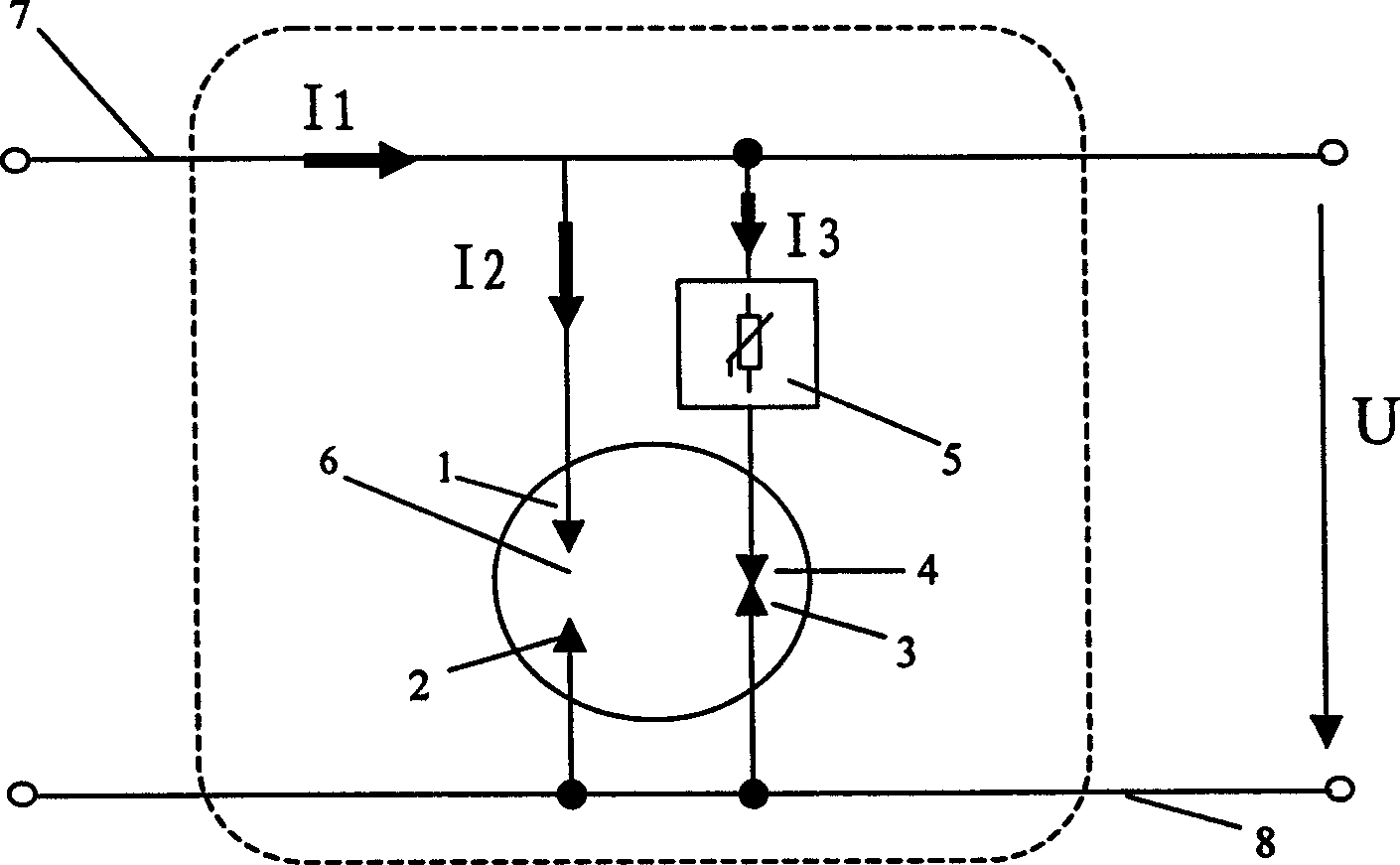
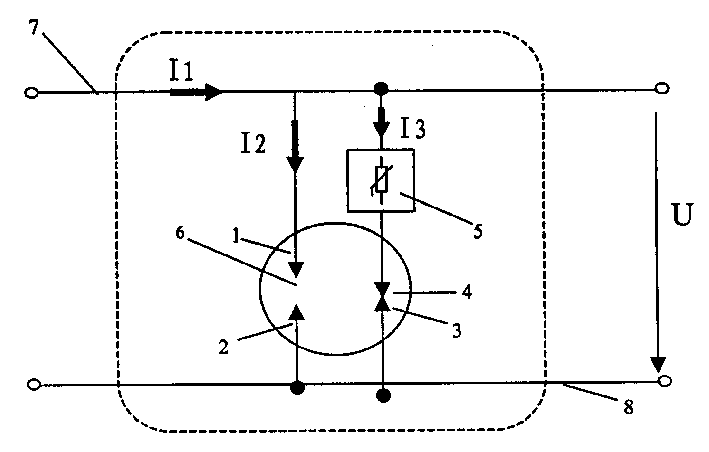
[0035] Depend on figure 1 It can be seen that there are two groups of surge protection circuits connected in parallel on the protected circuit 7 of the schematic diagram, one group is an auxiliary discharge circuit with trigger poles 3 and 4 and surge protection unit 5, and the other group is an auxiliary discharge circuit with a main discharge gap 6 And the main discharge line of the two electrodes 1 and 2.

[0036] A trigger unit 5 and a series connection of two trigger poles 3 , 4 capable of generating an arc are contained in the auxiliary discharge line with trigger poles 3 and 4 . Among them, the trigger unit 5 can use a solid discharge tube, a varistor, other surge protection components or a combination circuit of various surge protection devices; it can also be a series overload, short circuit protection unit or impedance. When the protected line has an overvoltag...


PUM


Abstract

The method consists of the assistant discharging circuit containing a group of trigger electrodes setup between protected circuits or devices and a ground electrode and the main discharging circuit containing a main discharging gap. The characters of the invention are that the distance setting between the trigger electrode and the main discharging gap is based on following consideration. The assistant discharging circuit containing trigger electrodes sets the overvoltage threshold. When voltage is higher than the threshold, electric surge current flows through the trigger pole to the ground electrode. The current passing through the trigger pole sets the current threshold. When current is larger than the current threshold, electric arc is generated and electric discharge happens in main discharging gap.

Description

technical field [0001] The invention relates to a surge protection technology, in particular to a surge protection method using gap discharge. Background technique [0002] Lightning activities, various operating overvoltages, and actions of electromagnetic pulse weapons, these powerful electromagnetic, voltage, and current changes instantaneously, generate various surge overvoltages and overcurrents on the surrounding conductors, and give electrical and electronic equipment, circuits harm and loss to people's lives and property. [0003] Through long-term practice, people have invented various surge protection devices to prevent losses caused by surges. For example, from the initial air gap to the current varistor, gas discharge tube, semiconductor discharge tube and the surge protection device formed by the simple combination of them, they have made great contributions to the protection against lightning and other surges. [0004] However, the above-mentioned components ...

Claims


Application Information

Patent Timeline
Patent Type & Authority Applications(China)
IPC IPC(8): H02H9/06
Inventor 黄兴英
Owner 黄兴英
Why Eureka
Try Eureka