Laser processing method and equipment

A laser processing method and laser processing technology, which are applied in laser welding equipment, metal processing equipment, welding equipment, etc., can solve the problems of gas shielding effect damage, inability to have, high airflow viscosity, etc., and reduce accidental scratches. Probability of machined surface, reduced manufacturing cost, high safety effect

Inactive Publication Date: 2003-12-10
V TECH CO LTD
View PDF1 Cites 10 Cited by
  • Summary
  • Abstract
  • Description
  • Claims
  • Application Information

AI Technical Summary

Problems solved by technology

However, the distance between the substrate surface and the gas envelope is usually only about 1 mm (this distance is related to the working range of the objective lens), so it is difficult to manufacture such a double gas flow path concentrically arranged around the laser irradiation part in the gas envelope
As a result, the manufacturing cost of the air bag body is high and the yield is low
In a high-precision laser processing device, high resolution requires a short working range, so the space required for the gas envelope cannot be guaranteed
This raises the question that high-precision processing devices cannot have such a transom
[0007] In addition, for the case where the concentric gas injection port and suction port are installed in the gas envelope, in order to increase the concentration of the source gas at the processing part and reduce the adsorption of fine particles generated at the processed part to the bottom, the source gas can be released from one Small-diameter nozzle ejection, so the source gas may have high gas flow viscosity in the laser irradiation part
In this case, the gas shielding effect of the nozzle is destroyed, so there will be problems such as source gas leakage to the surrounding and air mixing in.

Method used


Image

  • Laser processing method and equipment
  • Laser processing method and equipment
  • Laser processing method and equipment

Examples


Embodiment Construction

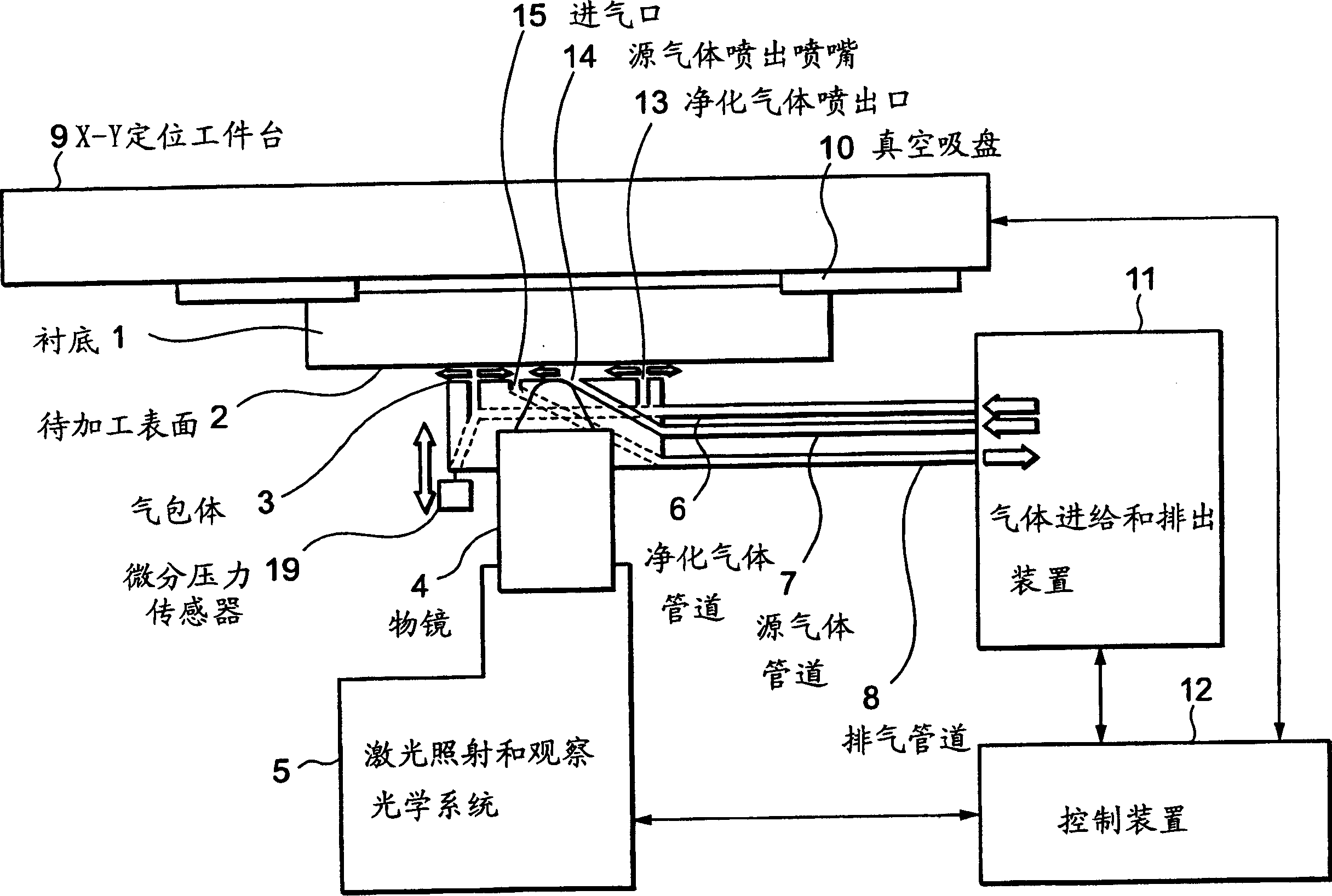
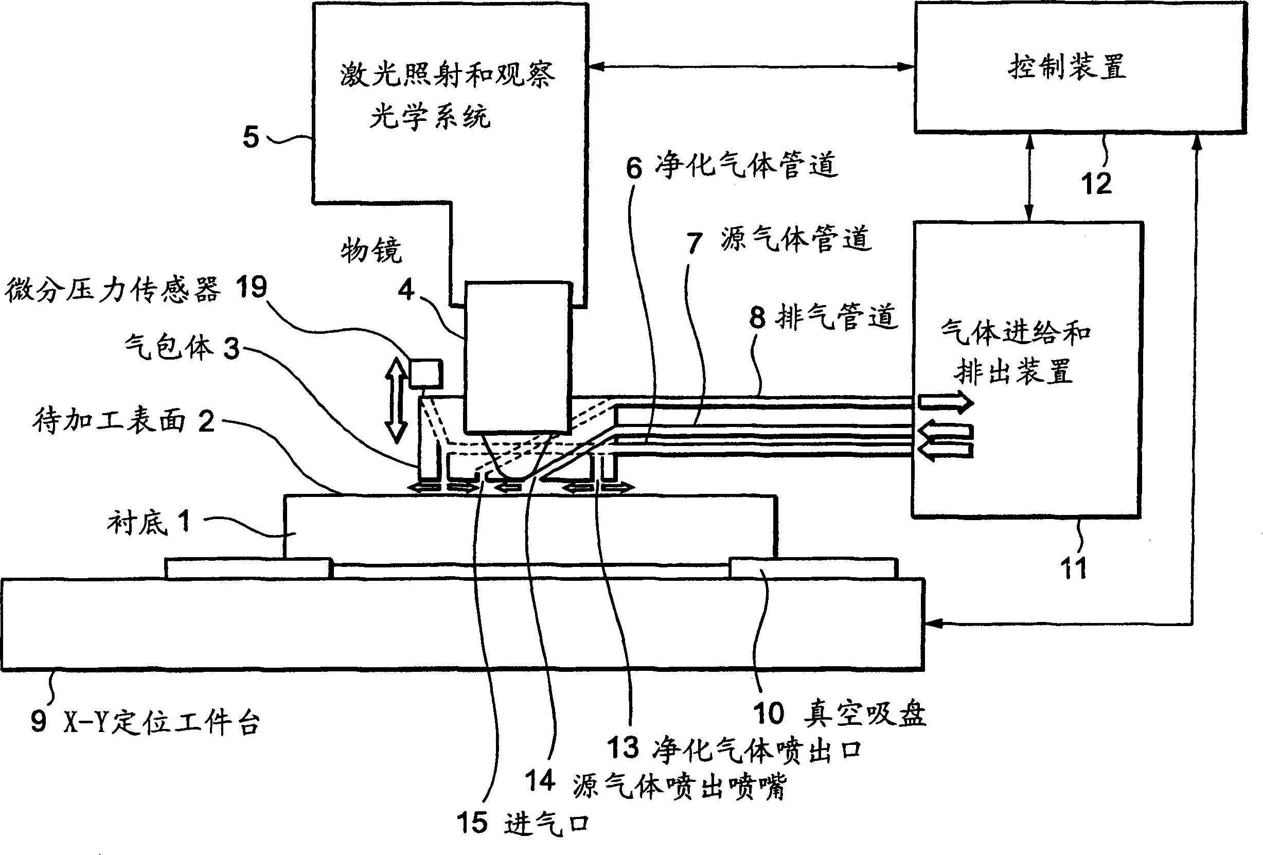
[0020] figure 1 It is a schematic structural diagram of a specific implementation device, showing the structure of the device used in the present invention for correcting transparent and opaque defects on the photomask.

[0021] In this figure, a substrate 1 including a photomask with a processed surface 2 facing downward is held by a vacuum chuck 10 on an X-Y positioning work table 9.

[0022] According to the movement of the X-Y positioning workpiece table, a laser irradiation and observation optical system 5 with an objective lens 4 at the top is used to observe the pattern on the lower surface of the substrate 1 and irradiate the lower surface with the laser beam.

[0023] The air bag 3 is located between the laser irradiation and observation optical system 5 and the substrate 1, and is used to guide the laser beam and introduce and discharge source gas. The objective lens 4 is integrated with the air bag body 3. The source gas pipeline 7 and the purified gas pipeline 6 are ...


PUM


Abstract

In a laser machining method for removing remaining defects on a photomask, there has been problems to be resolved that damage is formed at the portion of the substrate where the defect has been removed, thus resulting in degraded quality of machining. In a laser machining method for removing remaining defects on a photomask by a method of laser machining, the remaining defects are removed by using a configuration in which irradiation with a laser beam is performed from below with a to-be-machined surface directed downward, and irradiation with a laser beam in an atmosphere containing a halogenated hydrocarbon gas (as an example, ethyl iodide).

Description

Technical field [0001] The invention relates to a laser processing method for correcting pattern defects on a photomask and a liquid crystal substrate, and a laser processing device using the method. Background technique [0002] In Japanese Patent Application No. 2002-62637, a prior art laser processing apparatus for correcting pattern defects on photomasks and liquid crystal substrates is described. In the method for correcting pattern defects described in that application, the substrate is irradiated with a laser beam, and the processed surface of the substrate faces downward, so that the defects on the substrate are removed by laser evaporation. In this method, while the surface of the substrate is irradiated with the laser beam, it can be observed without reducing the resolution of the optical system used to observe it. In addition, since the fine particles produced by laser evaporation fall down under the action of gravity, high-precision patterns can be obtained, and the n...

Claims


Application Information

Patent Timeline
Patent Type & Authority Applications(China)
IPC IPC(8): B23K26/12C23F1/02C23F1/08G03F1/72H01L21/302
CPCB23K26/12B23K26/0853B23K26/1405B23K26/126C23F1/08G03F1/72C23F1/02B23K26/03B23K26/127B23K26/142G03F1/74
Inventor 森重幸雄
Owner V TECH CO LTD
Why Eureka
Try Eureka