Vacuum switchgear

A vacuum switch and equipment technology, which is used in the setting of electrical switches, switchgear with metal casings, high-voltage/high-current switches, etc. force, reliable tripping action, the effect of strengthening the joint strength

Inactive Publication Date: 2004-01-14
HITACHI LTD
View PDF1 Cites 5 Cited by
  • Summary
  • Abstract
  • Description
  • Claims
  • Application Information

AI Technical Summary

Problems solved by technology

[0006] However, although a vacuum gap is formed between the cylindrical insulator and the load-side electrode rod, the vacuum gap needs to be enlarged in order to relax the electric field concentration, and the overall diameter of the cable junction box including the load-side electrode rod and the cylindrical insulator is thick, Occupies more space and lower workability
Moreover, when t...

Method used


Image

  • Vacuum switchgear
  • Vacuum switchgear
  • Vacuum switchgear

Examples


Embodiment Construction

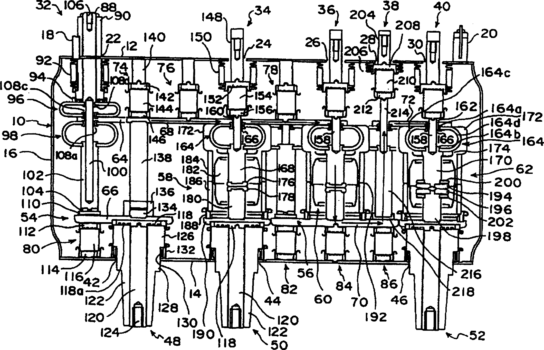
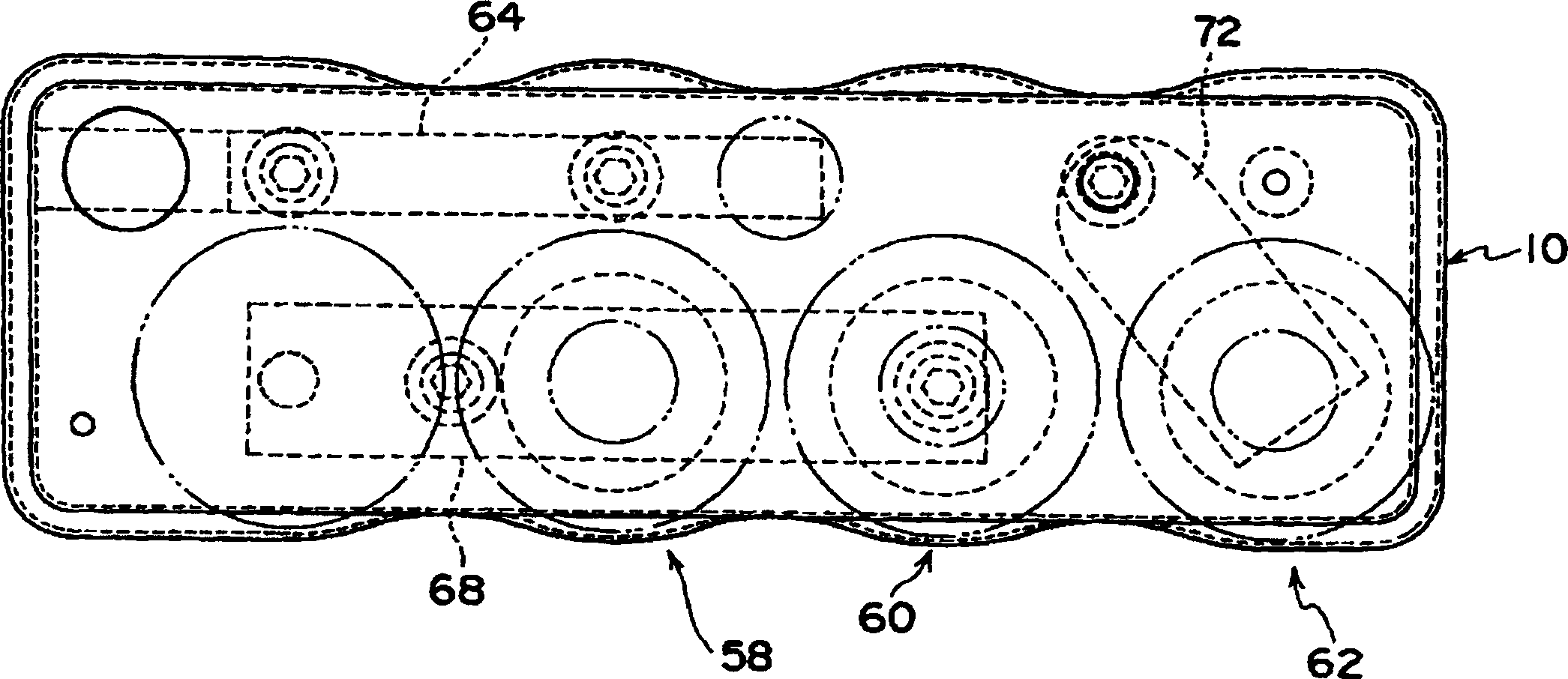
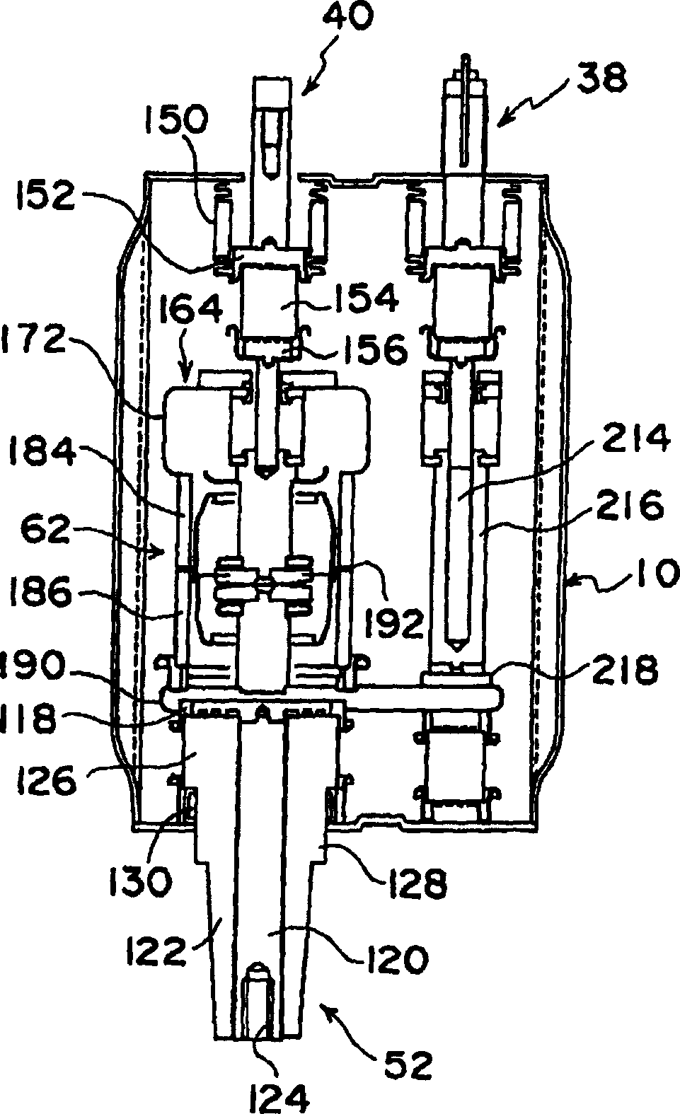
[0041] Hereinafter, an embodiment of the present invention will be described with reference to the drawings. figure 1 It is a front sectional view of main parts showing an embodiment of the vacuum switchgear of the present invention, figure 2 yes figure 1 The floor plan of the vacuum switchgear shown, image 3 yes figure 1 Side view of the vacuum switchgear shown, Figure 4 yes figure 1 The circuit diagram of the vacuum switchgear shown. exist Figure 1 to Figure 4 Among them, the vacuum switchgear is configured to include a vacuum container 10 made of stainless steel as one element of the power receiving and distribution equipment in the power distribution system. The vacuum container 10 has an upper plate 12, a lower plate 14, and a side plate 16. While the peripheries (edges) of the plates are joined to each other by welding, each part on one side of the side is stretched into a corrugated shape, so that even if the thickness of each plate is thinned, The plate thic...


PUM


Abstract

There is disclosed a vacuum switchgear, which comprises a vacuum container (10) to be earthed; a plurality of switches (58,60,62) disposed in the vacuum container. Each of the switches is so constituted that a movable electrode (176,194) supported by a movable electrode rod (168,170) and a fixed electrode (178,196) supported by a fixed electrode rod (180,198) are opposed to each other. One or more bus conductors (68,72) are connected to the movable electrode rod or the fixed electrode rod of each of the switches. Each of the switches comprises cylindrical insulating electrode shields (184,186) which are disposed around a conductive shield (182) surrounding the movable electrode and the fixed electrode. The insulating shield prevents scattering and adhere of metal vapor generated from the movable electrode and the fixed electrode.

Description

technical field [0001] The present invention relates to a vacuum switchgear, and in particular to a vacuum switchgear provided with a plurality of switches housed in a vacuum container and suitable for use as a power receiving and distributing device of an electric power system. Background technique [0002] A switchgear is installed in a power distribution system in an electric power system as one element of power receiving and distribution equipment. In the past, as this kind of switchgear, the air insulation method was often used, but in order to achieve miniaturization, SF is used as the insulating medium. 6 Gas-insulated method of gas. However, if SF is used in an insulating medium 6 Gases may have adverse effects on the environment. Therefore, in recent years, a vacuum insulation method using vacuum insulation as an insulating medium has been proposed. [0003] As a switchgear of a vacuum insulation method, for example, as described in JP-A-2000-268685 , a main circ...

Claims


Application Information

Patent Timeline
IPC IPC(8): H02B13/02H01H33/66H01H33/662
CPCH01H2033/6668H01H33/66261H01H2001/5827H01H33/66
Inventor 小林将人土屋贤治梶原悟喜久川修一清野拓也坂本芳树菅井大介
Owner HITACHI LTD
Why Eureka
Try Eureka