
Optical packaging equipment

A packaging device and optical technology, applied in the direction of lasers, laser components, semiconductor lasers, etc., can solve problems such as over-density pins, increase packaging volume, and affect the performance of optical components, so as to reduce parasitic capacitance and overcome short-circuit phenomenon Effect

Inactive Publication Date: 2004-01-14
FOXCONN (KUNSHAN) COMPUTER CONNECTOR CO LTD +1
View PDF1 Cites 1 Cited by
  • Summary
  • Abstract
  • Description
  • Claims
  • Application Information

AI Technical Summary

Problems solved by technology

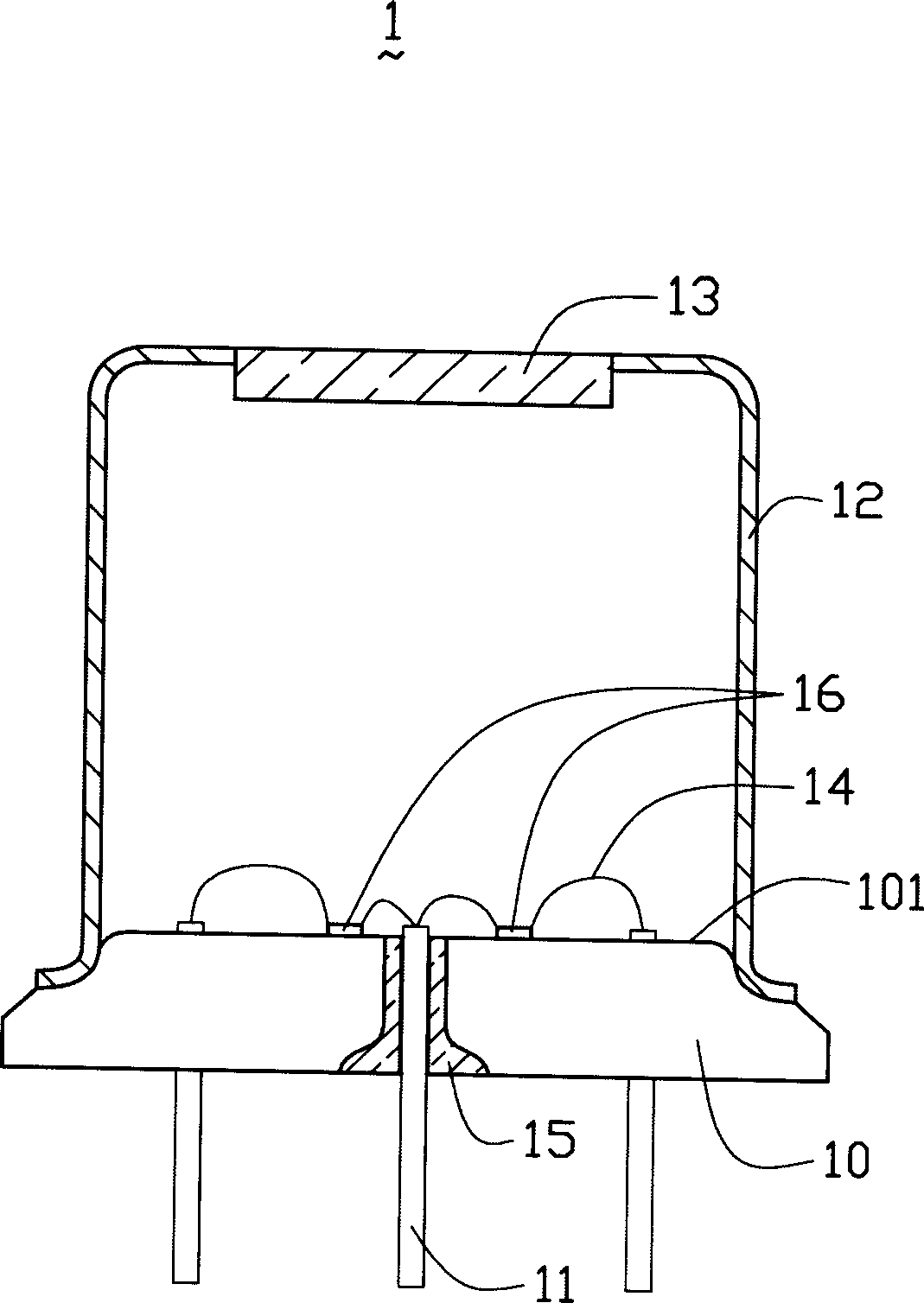
[0004] The optical package can basically realize the functions of fixing and sealing, but as the transmission rate and operating frequency increase, because the pins 11 and the wires 14 of the laser component 16 are relatively long, the inductance and capacitance will be parasitic and derived during high-frequency operation. Affect the working performance of optical components
Secondly, optical components tend to develop towards high integration and small volume. When the integration of optical components is high and a large number of electrical connections between internal components and external circuits are required, the number of pins and optical components must be increased accordingly. The package volume will further increase the parasitic and derived inductance and capacitance, and the pins are too dense, and if they are bent during operation, they are prone to short circuits

Method used


Image

  • Optical packaging equipment
  • Optical packaging equipment
  • Optical packaging equipment

Examples


Embodiment Construction

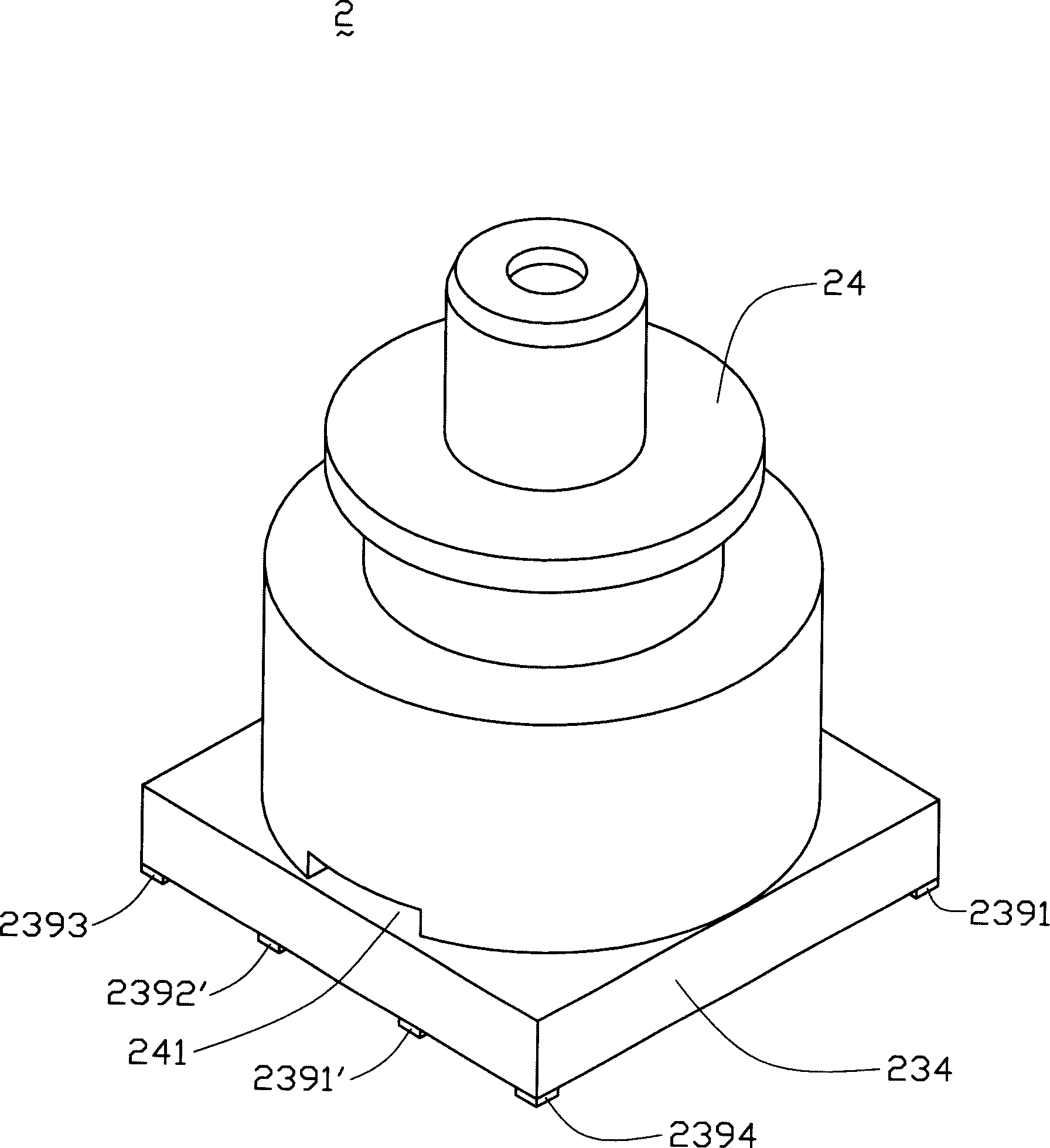
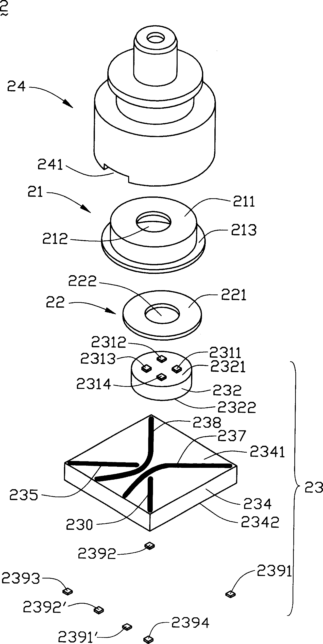
[0015] Please refer to figure 2 and image 3 The optical packaging device 2 of the present invention includes a cover body 21 , a lens component 22 , and a base 23 . The cover body 21 and the base 23 are tightly sealed to form a storage space for accommodating and protecting optical components (not shown) inside the optical packaging device 2 . The optical packaging device 2 further includes a connection part 24, which is located on the outside of the cover body 21, for connecting to an external light guide (such as an optical fiber) or other optical devices (not shown in the figure), and an opening 241 is provided at the bottom of the connection part 24 to facilitate Disassemble from the cover body 21.

[0016] The cover 21 is in the shape of a pot, generally made of metal material, and includes a top 211 and a bottom 213 . An opening 212 is disposed in the middle of the top 211 for transmitting or receiving light signals. The upper surface of the bottom edge 213 fits wit...


PUM


Abstract

An optical packing device used in the communication field comprising a cover member and a base which join tightly and form an accommodating space for holding the optical assembly, an opening is arranged on the cover member, a plurality of welding discs are arranged on the upper surface and the lower surface of the base, which are connected electrically by the printed circuit board formed on the base, and at least two welding discs on the lower surface connect each other. The optical packing device can be welded to the circuit board by the surface packing technology, the device is suitable for high density packing and high frequency operation and can facilitate the realization of the small scale packaging.

Description

【Technical field】 [0001] The invention relates to an optical packaging device applied in the communication field. 【Background technique】 [0002] With the development of science and technology, laser is widely used to obtain, transmit and store information, but its use requires a large number of optical devices or optical combinations, such as lasers, photodetectors, optical transceivers, etc. Such optical devices or optical combinations are relatively fragile, and external shocks and humid air will affect their performance and even cause damage, so they must be sealed in a package structure. However, some active devices in the optical combination need to be connected to external circuits or other devices through specific conductive structures. [0003] An optical packaging device as disclosed in U.S. Patent No. 5,812,582 (please refer to figure 1 ), which includes a laser component 16 and a can package for encapsulating the laser component 16, the can package includes a b...

Claims


Application Information

Patent Timeline
Patent Type & Authority Applications(China)
IPC IPC(8): H01S5/00H01S5/022
Inventor 牟忠信黄楠宗林永堂
Owner FOXCONN (KUNSHAN) COMPUTER CONNECTOR CO LTD
Learn More