
Electrostatic capacitor type pressure sensor and producing method thereof

A pressure sensor, electrostatic capacitance technology, applied in the fluid pressure measurement using capacitance change, fixing the capacitor terminal, measuring fluid pressure through electromagnetic components, etc., can solve the problems of difficult to obtain uniform detection accuracy, uneven distance, etc. The effect of uniform precision and small substrate area

Inactive Publication Date: 2004-01-21
ORMON CORP
View PDF3 Cites 11 Cited by
  • Summary
  • Abstract
  • Description
  • Claims
  • Application Information

AI Technical Summary

Problems solved by technology

[0006] However, in the above-mentioned pressure sensor, when the outer diameter of the substrate is small, it is necessary to arrange the sintering near the discontinuous spacer, and then the softened sintering flows in between the spacers and solidifies.
As a result, the distance between the fulcrums supporting the diaphragm as the substrate (which is elastically bent in the thickness direction by external pressure) is not uniform, and it is difficult to obtain uniform detection accuracy.

Method used


Image

  • Electrostatic capacitor type pressure sensor and producing method thereof
  • Electrostatic capacitor type pressure sensor and producing method thereof
  • Electrostatic capacitor type pressure sensor and producing method thereof

Examples


Embodiment Construction

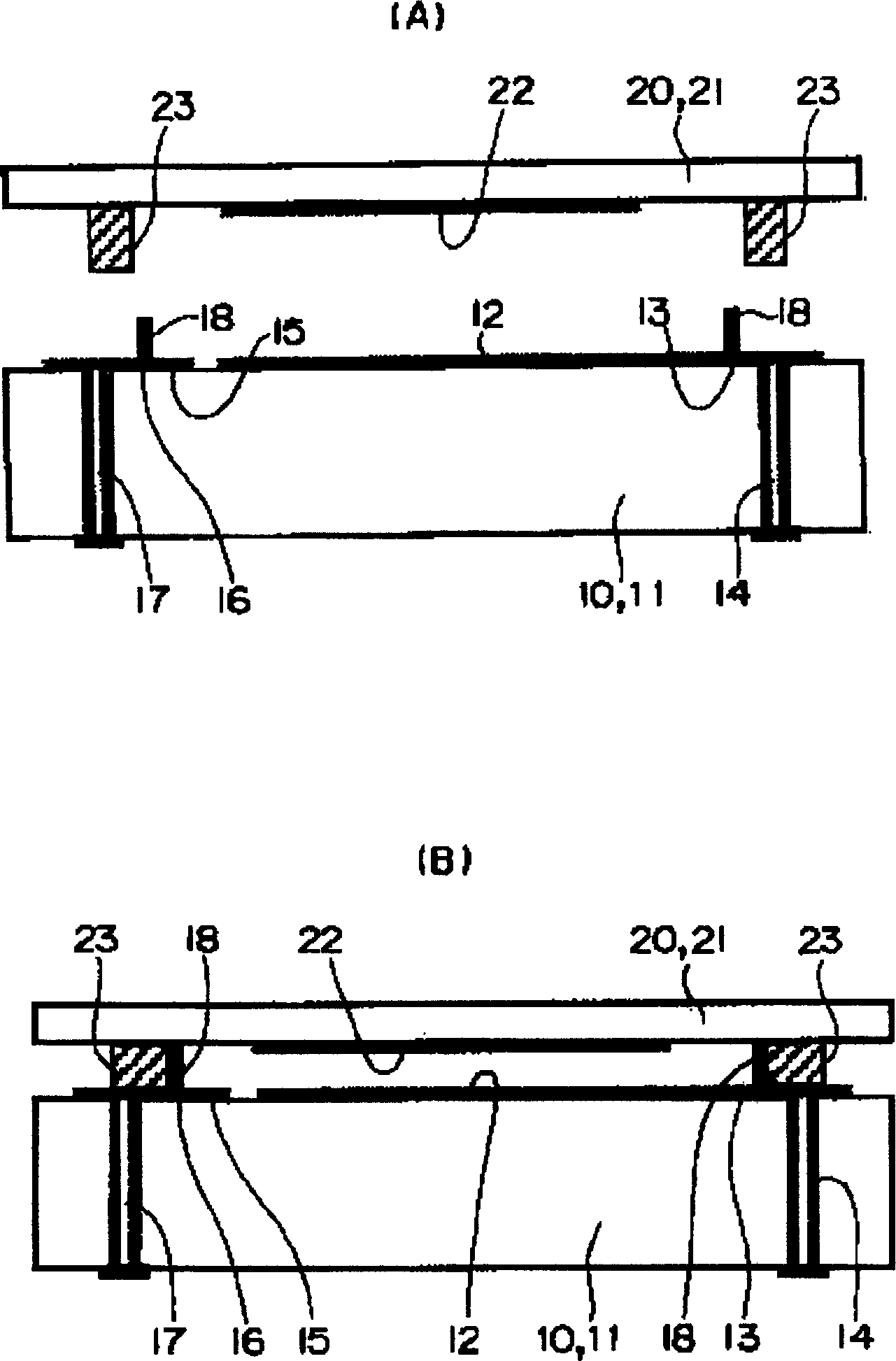
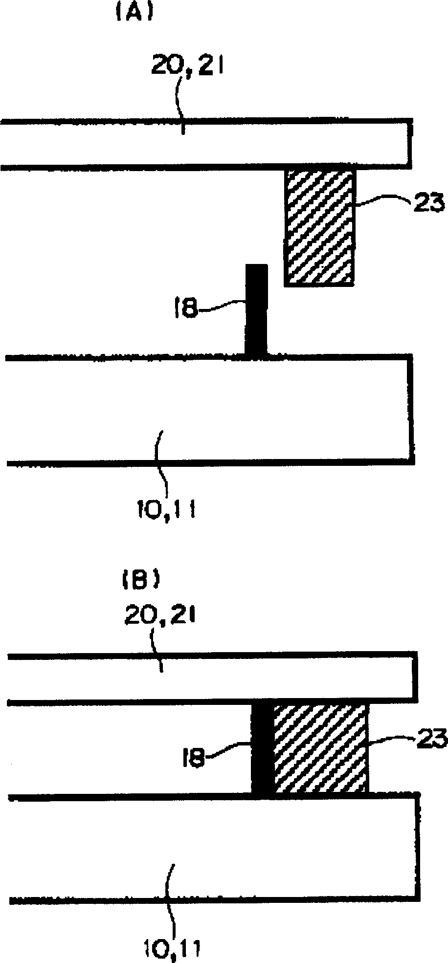
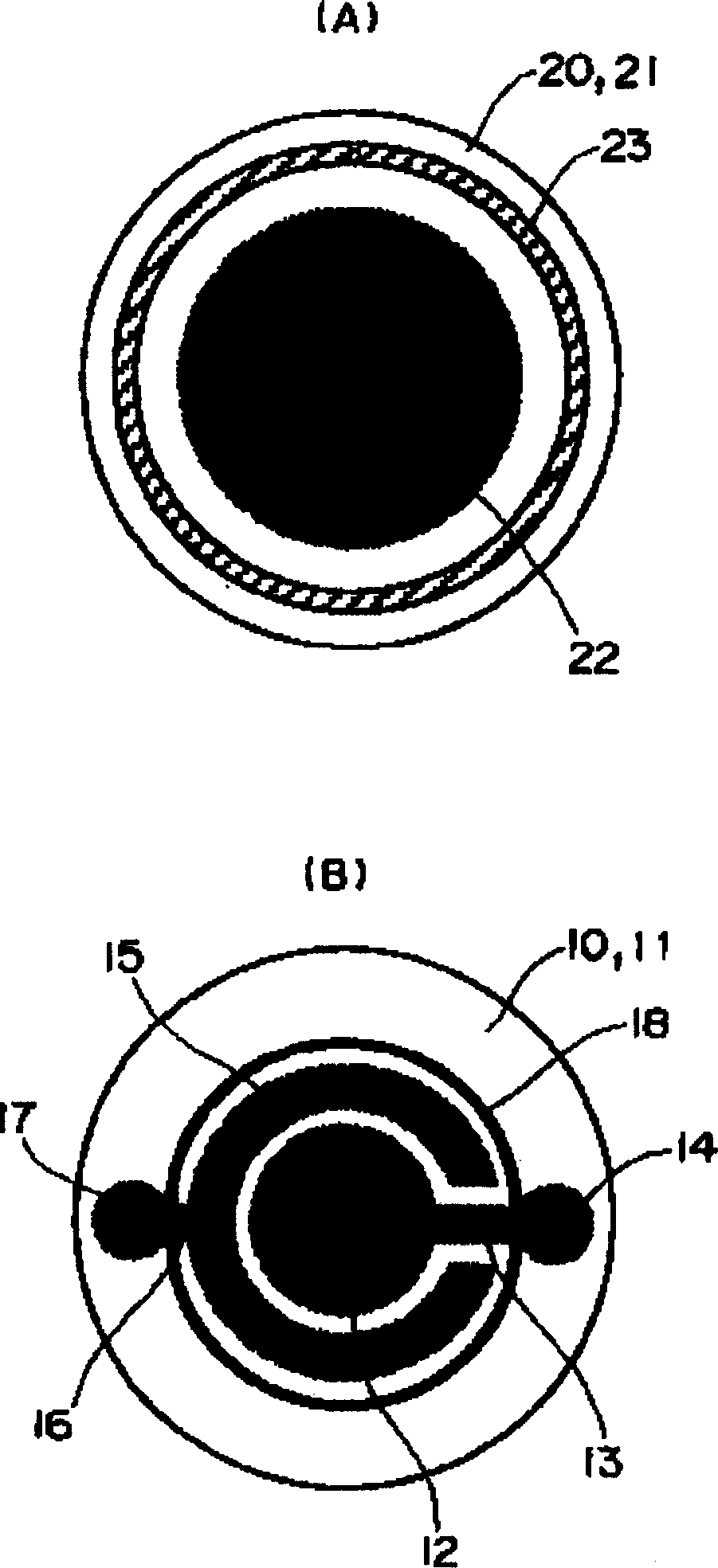
[0021] according to Figure 1 to Figure 6 The description relates to embodiments of the invention.

[0022] Such as Figure 1 to Figure 4 As shown, the first embodiment of the present invention relates to the case where the diaphragm 20 and the base 10 are joined together at a predetermined interval.

[0023] Such as image 3 As shown in B, the above-mentioned base 10 is provided with a first fixed electrode 12 at the center of the upper surface of a thick ceramic substrate 11 , and is connected to a through hole 14 through a lead wire 13 at the same time. Furthermore, the substantially C-shaped second fixed electrode 15 arranged around the first fixed electrode 12 is connected to the through hole 17 through the lead wire 16 . Therefore, an electrically conductive connection is formed from the underside of the ceramic substrate 11 through the through holes 14 and 17 , and the ring-shaped spacer 18 can be disposed around the second fixed electrode 15 .

[0024] The above-me...


PUM

PropertyMeasurementUnit
softening pointaaaaaaaaaa
melting pointaaaaaaaaaa

Abstract

The present invention provides a small-sized electrostatic condenser type pressure sensor having high assembly accuracy but no dispersion in a detection accuracy, and a method for manufacturing the pressure sensor. An annular spacer is mounted on the confronting faces of substrates around flat electrodes, and a frit is mounted around the spacer and is made of a material having a lower softening or melting point than that of the spacer.

Description

technical field [0001] The invention relates to an electrostatic capacitive pressure sensor and a manufacturing method thereof. Background technique [0002] Up to now, in capacitive pressure sensors, flat-plate electrodes are respectively provided on opposite surfaces of two substrates, so that the flat-plate electrodes face each other in parallel at a predetermined interval. Then, the pressure applied from the outside is detected by detecting the capacitance change caused by the elastic bending of one of the above-mentioned substrates in the thickness direction by the external pressure. [0003] Therefore, in order to achieve uniform detection accuracy, the distance between the opposing electrodes is extremely important. For this purpose, for example, JP-A-5-288623 and JP-A-10-111206 disclose a method of securing a predetermined inter-electrode gap using ceramic microballs or resin pellets, respectively. [0004] However, either method uses microspheres mixed in a fluid ...

Claims


Application Information

Patent Timeline
Patent Type & Authority Applications(China)
IPC IPC(8): G01L9/12G01L9/00
CPCG01L9/0075
Inventor 森下贞治外谷高志吉田伸辅野添悟史葛山大介
Owner ORMON CORP
Learn More