Water magnetizing device
A magnetized water and magnetic field technology, applied in the direction of magnetic field/electric field water/sewage treatment, etc., can solve the problems of low efficiency and large size of magnetized water
- Summary
- Abstract
- Description
- Claims
- Application Information
AI Technical Summary
Problems solved by technology
Method used
Image

Examples
Embodiment Construction
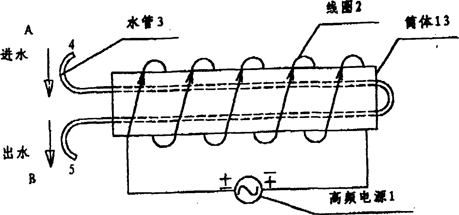
[0008] Please refer to the attached figure 1 As shown, a group of coils 2 are wound on a cylinder 13, and a high-frequency oscillation source 1 is connected to the coil 2 to generate an alternating magnetic field. In the space of simplified 13, it is passed into the water pipe 3, and the water to be treated comes from the inlet of the water pipe 3. 4 flows in and flows out from the water outlet 5. It can be seen that the direction of the water flow is parallel to the direction of the magnetic field lines generated by the coil 2.
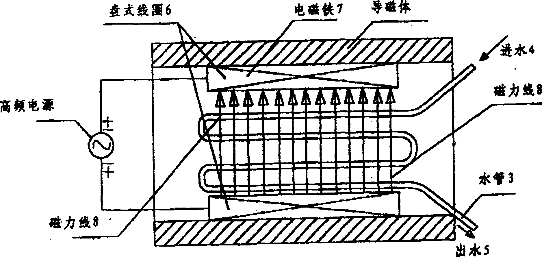
[0009] Please refer to the attached figure 2 As shown, an elliptical disc coil 6 is wound between the upper and lower electromagnets 7, and a layer of ferrite magnetic material is wrapped on the outermost layer to reduce magnetic flux leakage. Into the water pipe 3, the water to be treated flows in from the water inlet 4, and flows out from the water outlet 5. Coil 6 generates an alternating magnetic field. The direction of its magnetic force lin...
PUM
 Abstract
Description
Claims
Application Information