Gas subfebrile temperature in pression shaping method

A technology of micro-hot embossing and molding method, which is applied to other household appliances, optical components, household appliances, etc., can solve the problems of coral reefs, poor thickness uniformity, warping, etc., and achieves cost reduction, simplified manufacturing process, and excellent dimensional accuracy. Effect

Inactive Publication Date: 2004-03-03
张哲豪
View PDF3 Cites 28 Cited by
  • Summary
  • Abstract
  • Description
  • Claims
  • Application Information

AI Technical Summary

Problems solved by technology

However, in the electroforming process, due to the electrochemical reaction, a large number of various heavy metal electroforming acid solutions and various additives (such as stress relievers, detergents, wetting agents, etc.) are required. Difficult and expensive to dispose of, which greatly increases the burden on the environment
In addition, the electroforming process has many defects, such as replication efficiency, pinholes, warpage, surface accuracy, coral reefs, poor thickness uniformity, etc. There are still many problems to be solved

Method used


Image

  • Gas subfebrile temperature in pression shaping method
  • Gas subfebrile temperature in pression shaping method
  • Gas subfebrile temperature in pression shaping method

Examples


Embodiment 1

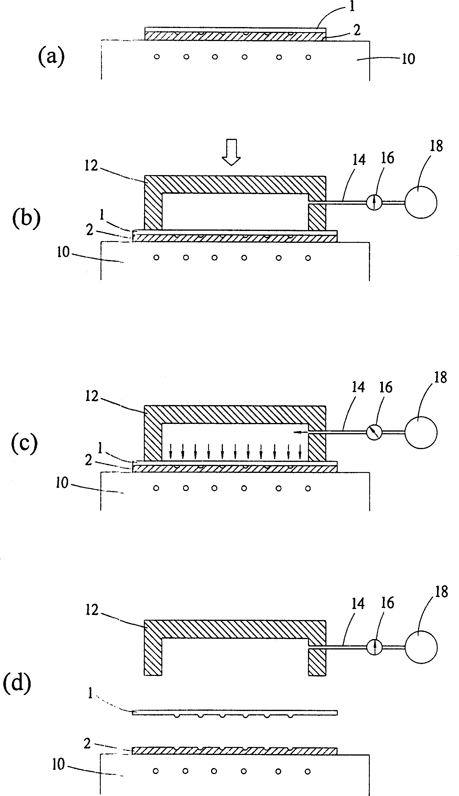
[0029] figure 1 (a) to 1(d) show the first embodiment of the gas microthermal imprint molding method according to the present invention. Such as figure 1 As shown in (a), the plastic film material (PC film) 1 as the mark to be imprinted is laid flat on the mold 2 with a predetermined microstructure in advance, and the side of the mold 2 with the microstructure and the mark to be imprinted To contact. The plastic / mold stacking combination formed in this way is set on the heating and cooling plate 10 as a workbench, and the heating and cooling plate can be used to heat and cool the plastic.

[0030] Then as figure 1 As shown in (b), a closed cavity 12 is covered on this plastic / mold stack combination, and the plastic / mold stack forms a closed space, and the closed cavity is connected to a hydraulic or crank (not shown in the figure) for rapid The airtight cavity is opened and closed. The sealed chamber is connected to a high-pressure gas compressor 18 and a pressure control valv...

Embodiment 2

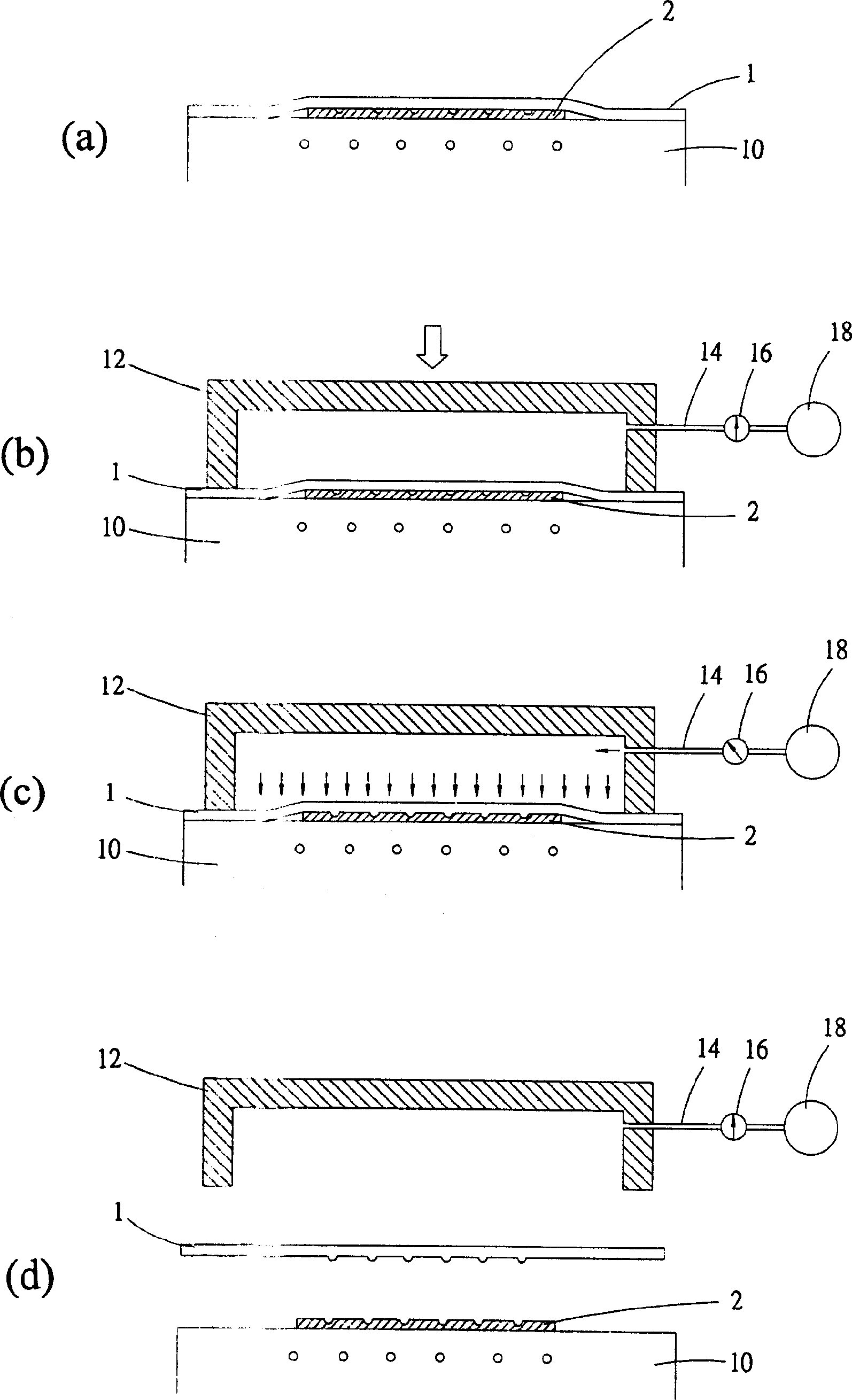
[0034] figure 2 (a) to 2(d) show the second embodiment of the gas micro hot stamping molding method according to the present invention, except that the hot stamping mold 2 used is a brittle material (such as a silicon wafer master mold, a glass master mold) And the sealed cavity 12 is to press the plastic film 1 as the mark to be imprinted to completely cover the mold 2 and the remaining part is not directly pressed on the mold 2. The other operation methods and conditions are the same as in the first embodiment.

Embodiment 3

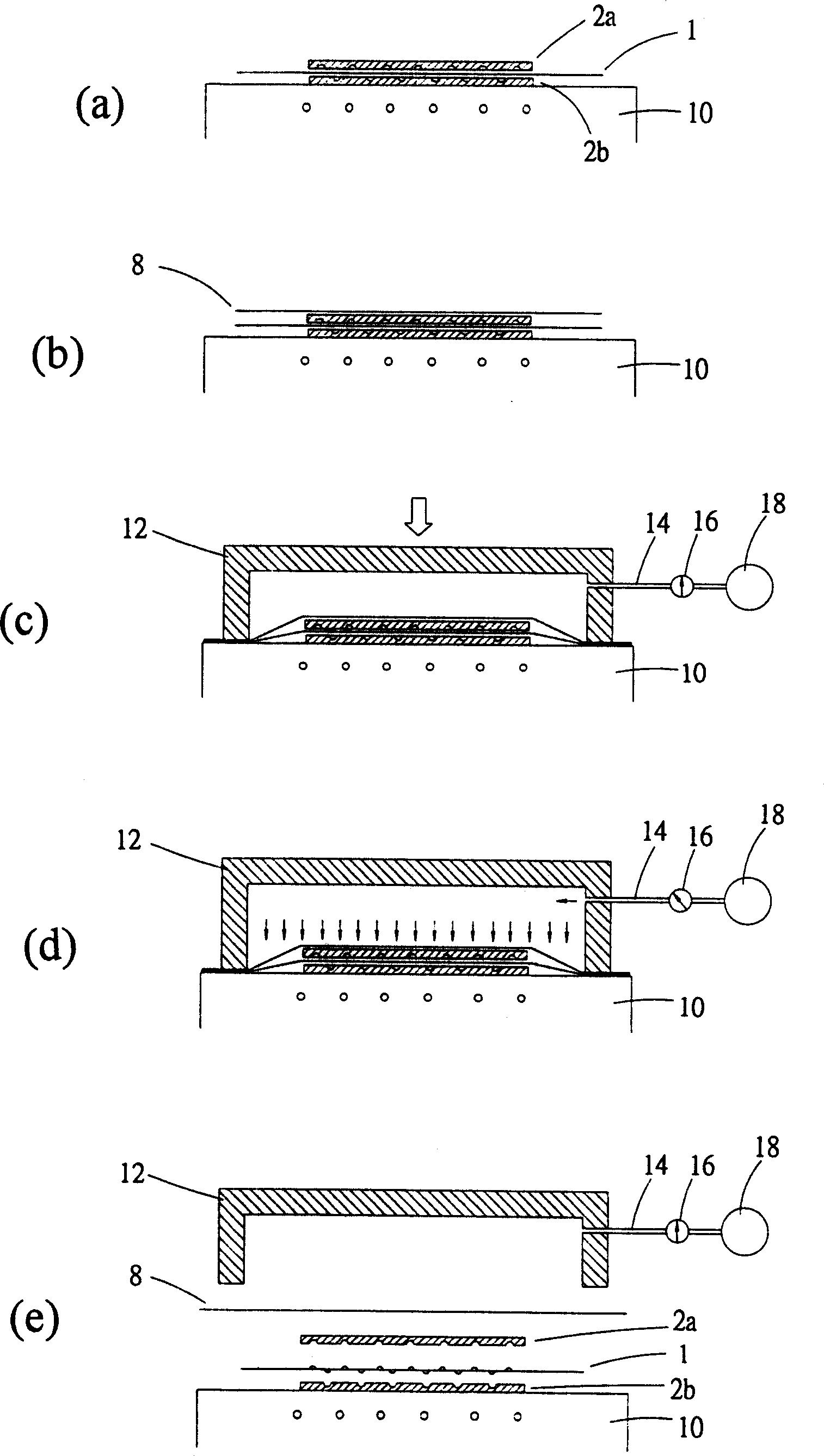
[0036] image 3 (a) to 3(e) show a third embodiment according to the present invention for molding a dual-surface microstructure element. Such as image 3 As shown in (a), the molding plastic film material (such as PC film) 1 as the mark to be imprinted is sandwiched between the upper and lower molds 2a and 2b to make it an upper mold / plastic film / lower mold Sandwich stacking combination. The upper mold and the lower mold respectively have microstructures formed on the upper mold. When forming a sandwich stack, the surfaces of the upper mold and the lower mold with the microstructures are opposed to each other, and the plastic film 1 is sandwiched between them. The sandwich stack combination of the upper mold / plastic film / lower mold is placed on a heating and cooling plate 10 as a workbench, and the heating and cooling plate 10 can be used to heat and cool the plastic.

[0037] Next, as shown in Figure (3b), a piece of sealing film 8 is laid flat on the sandwich stack combination...


PUM

PropertyMeasurementUnit
thicknessaaaaaaaaaa
thicknessaaaaaaaaaa
thicknessaaaaaaaaaa

Abstract

A high-pressure pneumatic hot embossing technology for shaping the object includes such steps as laying an object to be embossed on a die, covering it with a sealed cavity to form a sealed space, heating to make it become plastic state, and introducing high-pressure air in it.

Description

(1) Technical field [0001] The invention relates to a gas micro-heat embossing forming method of a microstructure. (2) Background technology [0002] Since the 1990s, the development of Micro-Electro-Mechanical Systems (MEMS) has attracted much attention all over the world. It includes the technical integration of multiple technologies such as machinery, optics, electronics, materials, control, and chemistry. It is hoped that the use of this new manufacturing technology can miniaturize products and improve their performance, quality, reliability and added value, while reducing production costs and energy consumption, making production and life applications more convenient. [0003] The hot embossing method (Hot Embossing) is the main microstructure replication (Replication) technology in the field of microelectromechanical systems, in which the microstructure refers to the size measurement unit in μm or nm. The resulting microstructures can be used directly as components or used ...

Claims


Application Information

Patent Timeline
Patent Type & Authority Applications(China)
IPC IPC(8): B29C33/24B29C43/02B29C43/10B29C43/56B29C59/06
CPCB29C2043/3238B29C43/10B29C2043/3647B29C2043/025B29C2043/3649B29C43/021B29L2011/00
Inventor 张哲豪杨申语
Owner 张哲豪
Why Eureka
Try Eureka