Method of treating oil containing waste water using anion cation mixed ion resin
A technology of mixed ion resin, anion and cation, applied in the field of environmental technology and chemical separation, can solve the problems such as the need to improve the packing, the need to improve the treatment effect, and the low energy consumption of the coarse-grained method
- Summary
- Abstract
- Description
- Claims
- Application Information
AI Technical Summary
Problems solved by technology
Method used
Image

Examples
Embodiment 1
[0015] Influence test of inlet liquid temperature on oil-water separation.
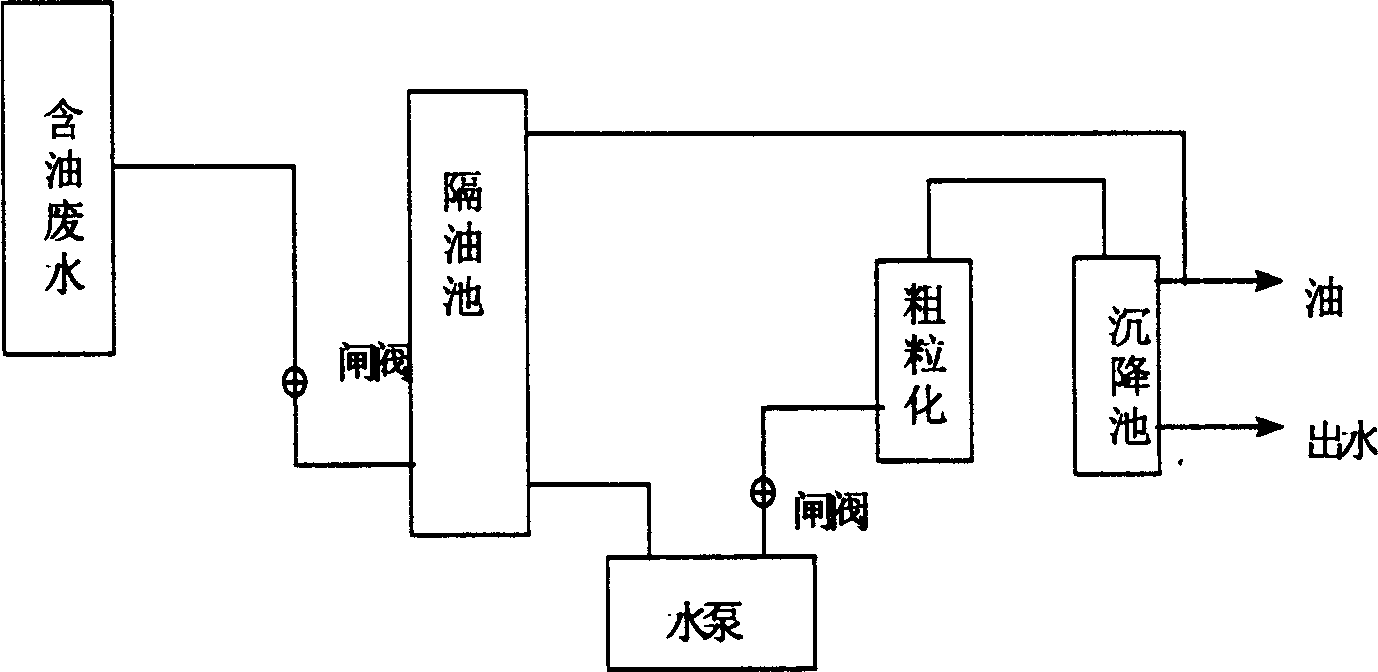
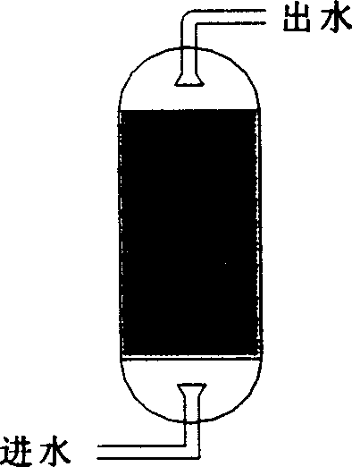
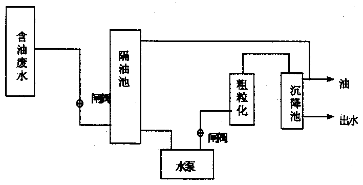
[0016] The oily wastewater first flows through the gate valve through the grease trap and enters the high-pressure pump, and then enters the coarse granulation device through the gate valve. The anion and cation resin columns used in the coarse granulation device are 50cm in height and 3cm in diameter, and the anion resin uses strong alkali Strong styrene-based anion exchange resin 201×7 (717); cationic resin adopts strongly acidic styrene-based cation-exchange resin 001×7, and the ratio of anion and cation resins is 1:1. The content of the feed oil entering the anion and cation resin column is 500mg / L, and the flow rate of the feed liquid is 10L / H, and finally the oil-water separation is completed through the settling tank. The inlet liquid temperatures were 20°C, 40°C, and 60°C, and the stabilization time was 5 hours. The corresponding oil contents in the outlet liquids were 13.71mg / L, 11.05mg / L, an...
Embodiment 2
[0018] Influence test of liquid inlet stabilization time on oil-water separation.
[0019] The oily wastewater first flows through the gate valve through the grease trap and enters the high-pressure pump, and then enters the coarse granulation device through the gate valve. The anion and cation resin columns used in the coarse granulation device are 50cm in height and 3cm in diameter, and the anion resin uses strong alkali Strong styrene-based anion exchange resin 201×7 (717); cationic resin adopts strongly acidic styrene-based cation-exchange resin 001×7, and the ratio of anion and cation resins is 1:1. The content of oil entering the anion-cation resin column is 500mg / L, the flow rate of the liquid is 10L / H, the temperature of the liquid is 10-20°C, and finally the oil-water separation is completed in the settling tank. The running time is 1 hour, 2 hours, 3 hours, 4 hours, and 5 hours respectively, and the corresponding oil content in the effluent is 15.6mg / L, 14.2mg / L, 14....
Embodiment 3
[0022] The technological process and equipment are the same as above, using old anion-cation resins as fillers for wastewater treatment, wherein the ratio of anion-cation resins is 1:1, the water temperature is 20°C, the influent flow rate is 10L / H, and the oil content in the influent water is 500mg / L. The oil content in the effluent was 28.25 mg / L, and the oil removal rate was 94.35%. It can be seen that the effect of using old anion and cation resins is also about 95%, so the waste and old anion and cation resins can be used to treat oily wastewater, and the purpose of treating waste with waste is realized.
PUM
 Abstract
Description
Claims
Application Information
 - R&D
- Intellectual Property
- Life Sciences
- Materials
- Tech Scout
- Unparalleled Data Quality
- Higher Quality Content
- 60% Fewer Hallucinations
Browse by: Latest US Patents, China's latest patents, Technical Efficacy Thesaurus, Application Domain, Technology Topic, Popular Technical Reports.
© 2025 PatSnap. All rights reserved.Legal|Privacy policy|Modern Slavery Act Transparency Statement|Sitemap|About US| Contact US: help@patsnap.com