Transforming device of push-pull circuit type

A technology of a substation and a push-pull circuit, which is applied to the conversion device of output power, the adjustment of electric variables, and the conversion equipment with intermediate conversion to AC, etc., to achieve the effect of realizing the device

Inactive Publication Date: 2004-03-03
ORMON CORP
View PDF0 Cites 14 Cited by
  • Summary
  • Abstract
  • Description
  • Claims
  • Application Information

AI Technical Summary

Problems solved by technology

In this method, a CT is inserted into the primary of the transformer, and the primary current must be monitored at all times, so...

Method used


Image

  • Transforming device of push-pull circuit type
  • Transforming device of push-pull circuit type
  • Transforming device of push-pull circuit type

Examples


Embodiment Construction

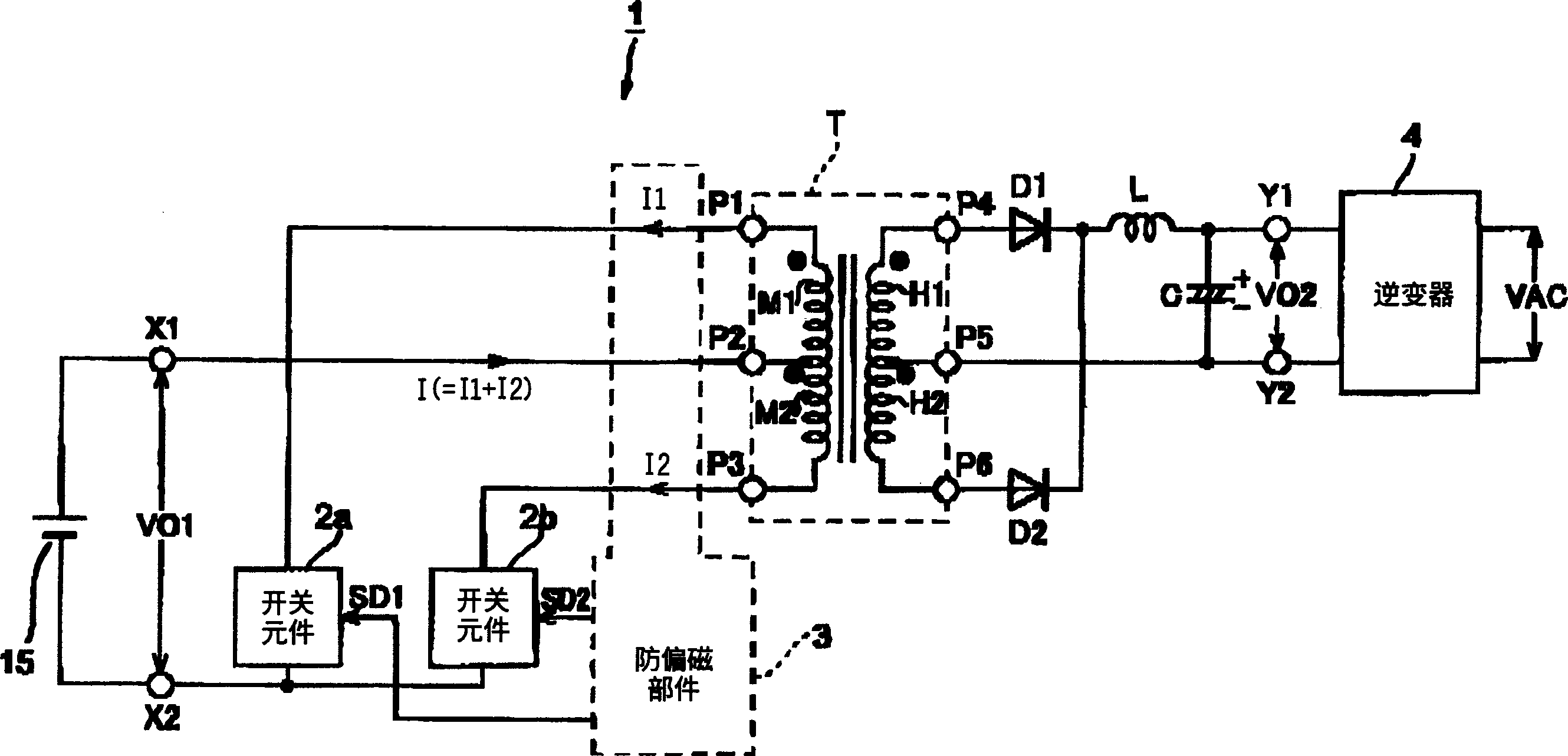
[0024] Hereinafter, embodiments of the present invention will be described with reference to the drawings. figure 1 It is a basic block configuration diagram of an embodiment of the push-pull circuit type power conversion device of the present invention. figure 1 Among them, the power conversion device 1 is provided with a switching element 2a, a switching element 2b, a pulse transformer T, a rectifying diode D1, a rectifying diode D2, a choke coil L, a smoothing capacitor C and anti-bias components constituting a push-pull inverter. 3. Inverter 4; convert the DC power source 15 (DC voltage V01) such as a solar cell or a fuel cell into a high-frequency pulse and input it to the primary of the pulse transformer T, and take out the high-frequency pulse from the secondary insulated (isolated) from the primary After performing rectification and smoothing and filtering to form a DC power supply (DC voltage V02 ), it is converted into an AC power supply (for example, 50Hz / 200V) by t...


PUM


Abstract

An electric power conversion device comprises switching elements 2a, 2b making up a push-pull converter, a pulse transformer T, a rectification diode D1, a rectification diode D2, a choke coil L, a smoothing capacitor C, a DC magnetic deviation prevention means 3, and an inverter 4. The DC magnetic deviation prevention means 3 detects the coil currents I1, I2 flowing in the primary windings M1, M2 of the pulse transformer T. By controlling (shortening) the on time of the switching element having a greater amount of current, the coil currents I1, I2 are balanced (I1=I2), thereby preventing the magnetic deviation phenomena of the pulse transformer.

Description

technical field [0001] The present invention relates to a push-pull circuit method that converts a direct current power source such as a solar battery or a fuel cell into a high-frequency pulse by on / off switching, and then rectifies and smoothes the high-frequency pulse through a pulse transformer to generate direct current. The invention relates to an electric device, in particular to a push-pull circuit-type power transformation device capable of preventing a bias phenomenon of a pulse transformer caused by an unbalanced current in a push-pull circuit. Background technique [0002] In recent years, due to the decentralized power supply that converts the DC power obtained by solar cells or fuel cells into AC power and the mains network, the distributed power supply is used to supply power to devices (loads) in the home, while the decentralized power supply cannot supply power. In this case, a system with a so-called system interlock device powered from the mains is provide...

Claims


Application Information

Patent Timeline
IPC IPC(8): H02M3/28H02M3/337
CPCH02M3/3372H02M2007/4803H02M7/4803
Inventor 田边胜隆豊浦信行冈诚治马渕雅夫中村耕太郎鹤川优治井上健一
Owner ORMON CORP
Why Eureka
Try Eureka