
Glass substrate and glass cutting method

A glass substrate and glass cutting technology, applied in glass cutting devices, glass production, glass manufacturing equipment, etc., can solve the problems of small cracks and broken glass, disadvantages, etc., achieve light weight, increase productivity and yield, and increase strength Effect

Inactive Publication Date: 2004-03-10
DEXERIALS CORP
View PDF4 Cites 6 Cited by
  • Summary
  • Abstract
  • Description
  • Claims
  • Application Information

AI Technical Summary

Problems solved by technology

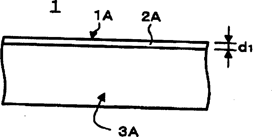
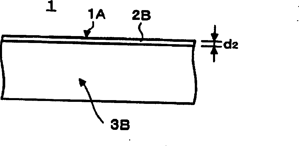
[0009] However, if a cutting method with only ordinary laser rays is used on the cut side of the glass substrate 1 formed by irradiating laser light, such as Figure 8 As shown in the illustrated schematic cross-sectional structure, micro cracks and broken glass are disadvantageously generated in the laser mark 2 appearing from the laser irradiation side

Method used


Image

  • Glass substrate and glass cutting method
  • Glass substrate and glass cutting method
  • Glass substrate and glass cutting method

Examples


Embodiment Construction

[0046] Embodiments of the glass substrate and glass cutting method of the present invention, and comparative examples based on the embodiments will be described in detail below with reference to the accompanying drawings. In the following embodiments, a case where the present invention is applied to a glass substrate of a portable terminal equipped with a touch panel, and a cutting method for obtaining such a glass substrate will be described. However, it is obvious that various changes and modifications can be made unless the invention departs from the scope of the present invention.

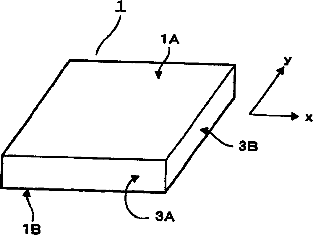
[0047] exist Figures 1A to 1D In , a schematic structure of a glass substrate based on the structure of the present invention is shown. In addition to Na, K and SiO 2 In addition to the so-called soda glass, non-alkali glass can also be used as the material of the glass substrate 1 .

[0048] Such as Figure 1A As shown, a glass substrate 1 has a first major surface 1A and a second major s...


PUM

PropertyMeasurementUnit
surface roughnessaaaaaaaaaa
depthaaaaaaaaaa
strengthaaaaaaaaaa

Abstract

A glass substrate excellent in strength properties and a glass cutting method are provided. When a glass substrate having predetermined size is to be formed by cutting a glass plate, any crack or chip is not generated on a cut face. Therefore, a pulverized powder is prevented from being generated from this portion. A glass substrate is obtained by cutting at least with laser light radiation so that a surface roughness of cut side faces and of the glass substrate are 50 nm or less and a depth of laser marks and on the cut side faces are 0.06 mm or more.

Description

[0001] Cross References to Related Applications [0002] This application is based on Japanese Priority Document JP2002-215760 filed with Japan Patent Office on July 24, 2002, which is incorporated herein by reference in its entirety. technical field [0003] The present invention relates to a glass substrate formed by cutting glass with laser irradiation and forced cooling, and to a glass cutting method. Background technique [0004] For a glass cutting method of vertically and horizontally cutting a glass plate to produce a glass substrate having a predetermined width and length, a mechanical cutting method as described in Japanese Patent Laid-Open Publication No. 11-71124, or a laser cutting method using laser rays is generally used. [0005] In the case of cutting methods with a mechanical process, the glass is cut by pressing the blade against the glass to create an intermediate crack, ie a crack that propagates perpendicularly to the glass surface. In this cutting met...

Claims


Application Information

Patent Timeline
Patent Type & Authority Applications(China)
IPC IPC(8): B28D1/22B23K26/14B23K26/364B23K26/38B23K26/40C03B33/07C03B33/09G06F3/041
CPCY10T428/24479C03B33/033Y10T428/24488Y10T428/24355C03B33/091C03B33/07Y02P40/57C03B33/09
Inventor 平野富男及川信幸小野寺牧夫小野正男佐藤英樹小野寺幸広
Owner DEXERIALS CORP
Learn More