Appts for cleaning edges of wafers

A wafer and edge technology, applied in the field of wafer cleaning devices, can solve problems such as damage, reduced wafer productivity, and increased manufacturing costs

Inactive Publication Date: 2004-03-10
K C TECH
View PDF1 Cites 16 Cited by
  • Summary
  • Abstract
  • Description
  • Claims
  • Application Information

AI Technical Summary

Problems solved by technology

[0010] However, this traditional device for cleaning the edge of the wafer adopts a plurality of shaft rollers and motors for driving the shaft rollers for cleaning the edge of the wafer. Therefore, the structure is complicated, and the manufacturing cost is increased, and the brushes constructed by mechanical methods may pass through the contact surface on the wafer. In addition, the wafer may be re-contaminated by the cleaning liquid contaminated after cleaning the wafer edge, reducing the productivity of the wafer

Method used


Image

  • Appts for cleaning edges of wafers
  • Appts for cleaning edges of wafers
  • Appts for cleaning edges of wafers

Examples


Embodiment Construction

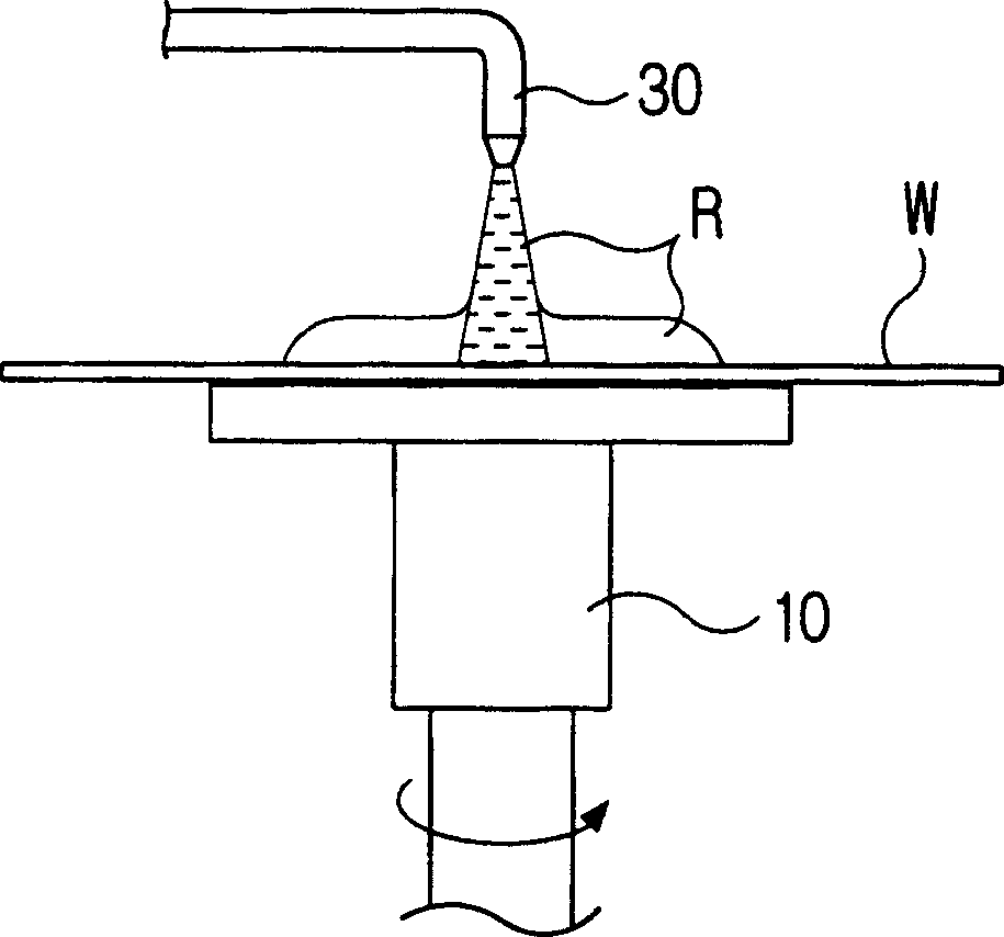
[0035] image 3 It is a schematic diagram of cleaning the edge of the wafer by the dry cleaning process using dry ice of the present invention.

[0036] Such as image 3 As shown, the device for cleaning the edge of the wafer of the present invention is arranged on a side portion of a wafer (W) held by suction by a rotary chuck 10, and the device for cleaning the edge of the wafer includes a jet of solidified carbon dioxide CO that is converted into particles. 2 (referred to as dry ice) nozzle body 1, and a nozzle body holder 2 that moves the nozzle body 1 between a rest position and a cleaning position. The nozzle body holder 2 (referred to below as a pneumatic cylinder) is shown in the figures as a pneumatic cylinder, but may include a stepper motor. The nozzle body 1 has a lower bracket 5 connected to the piston 4 of the pneumatic cylinder 2, which is mounted to the cleaning device via a bracket 6 arranged on the side part of the rotary chuck 10.

[0037] When the spin c...


PUM


Abstract

The invention concerns an apparatus for cleaning the edge of a wafer that may be relatively simply constructed with low cost, and prevent the wafer from being re-contaminated by the edge cleaning, thus resulting in increase of the yield rate of wafers. The apparatus includes a cleaning agent ejection nozzle body provided on a side part of a chuck for ejecting a particulate cleaning agent (CO2 particles) towards the side and the edge portions of the wafer held and rotated by the chuck, and a nozzle body carriage for moving the nozzle body between rest and cleaning positions.

Description

technical field [0001] The present invention relates to a device for cleaning wafers, more particularly to a device for cleaning the edges and sides of wafers with tiny solid volatile particles, such as dry ice. Background technique [0002] The process of manufacturing a semiconductor device uses an apparatus for cleaning a semiconductor wafer (hereinafter simply referred to as a wafer) having a thin film circuit pattern on its surface. [0003] Conventional wafer cleaning devices such as figure 1 shown. The apparatus includes a spin chuck 10 that holds the wafer (W) substantially horizontally by suction and rotates the wafer, and a spin chuck 10 that is arranged above the center of rotation of the spin chuck to supply a cleaning or treating liquid to the surface of the wafer (W). The treatment liquid is supplied to the nozzle 30 . [0004] First, a motor (not shown) drives the spin chuck 20 to rotate the wafer (W) at a predetermined speed, and when the rotation is stabl...

Claims


Application Information

Patent Timeline
Patent Type & Authority Applications(China)
IPC IPC(8): H01L21/304B08B7/00B24C1/00B24C3/02B24C3/22H01L21/00H01L21/306
CPCB08B7/0092B24C1/003B24C3/02B24C3/22H01L21/67051Y10S134/902H01L21/02052H01L21/304
Inventor 高世钟金重琯尹哲男李正浩
Owner K C TECH
Why Eureka
Try Eureka