Manufacturing process and installation for the thin bolt with spanner pilot hole and hexangular socket head

A manufacturing method and technology of guide holes, which are applied in the field of screw manufacturing, can solve problems such as the deviation of the drill axis of the drill bit, the angle of the edge trimming of the drill lip is not correct, and the reduction of the use effect, so as to shorten the working time, reduce defective products, The effect of reducing the defective rate

Inactive Publication Date: 2004-03-17
FUGUANG ENTERPRISE
View PDF0 Cites 11 Cited by
  • Summary
  • Abstract
  • Description
  • Claims
  • Application Information

AI Technical Summary

Problems solved by technology

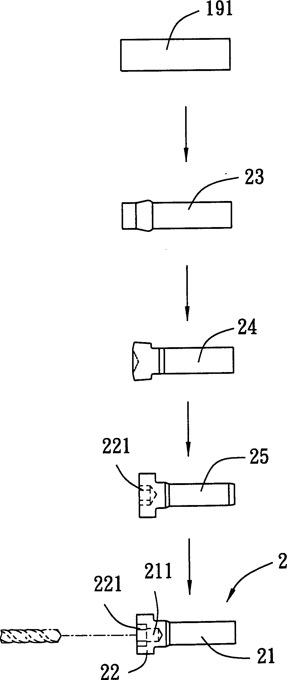
[0005] When the guide hole 211 of the above-mentioned blank is drilled, the processing personnel must use the above-mentioned large number of forged parts to cooperate with the drilling machine to drill them into the screw 2 with the guide hole 211 in a semi-manual way. Waste of manpower and man-hours
In addition, in the drilling process of the above-mentioned screw 2, it is easy to cause the guide hole to be formed due to factors such as the drill bit of the drilling machine located at the tail end of the drill lip trimming angle is not correct, or the drill axis of the drill bit is not straight, or the processing personnel do not operate properly. 211 Absence of poor alignment of the center
At present, in the screw manufacturing industry, the tolerance of the guide hole 211 is very small, which is 0.06-0.09mm. Therefore, the accuracy of manufacturing the guide hole 211 must be relatively improved. However, if the center of the guide hole 211 is skewed, Or when the hole size error of the pilot hole 211 is large due to drilling processing factors, the screw 2 becomes a defective product that cannot be used. Therefore, the previous manufacturing method has the defects of high defect rate and high cost.
[0006] like Figure 4 As shown, in order to avoid the above-mentioned problems in the processing of the guide hole 211, some manufacturers have considered that if the shape of the third punch 171 is changed, a section of pointed column 172 protrudes from the rear end of the third punch 171, A multi-layer step-shaped punch can directly punch and forge the inner hexagonal hole 221 and the guide hole 211 on the third blank 25. In addition to solving the above-mentioned defects, the manufacturing process can be reduced, but the cross-section is The difference in area between the hexagonal third punch 171 and the pointed column rod 172 with a circular cross section is too large, resulting in the concentration of applied stress at the junction between them, and in actual forging, because the third pun

Method used


Image

  • Manufacturing process and installation for the thin bolt with spanner pilot hole and hexangular socket head
  • Manufacturing process and installation for the thin bolt with spanner pilot hole and hexangular socket head
  • Manufacturing process and installation for the thin bolt with spanner pilot hole and hexangular socket head

Examples


Example Embodiment

[0031] Such as Figure 5 , Figure 6 and Figure 7 As shown, the first preferred embodiment of a screw manufacturing device of the present invention includes a machine 3, a first female mold 41, a second female mold 42, and a second female mold 42 that are sequentially installed on the machine 3 A third female mold 43 and a fourth female mold 44, and a first male mold correspondingly located in front of the female molds 41-44 and capable of being driven by a power source to reciprocately press the female molds 41-44 Mold 51, a second male mold 52, a third male mold 53, and a fourth male mold 54. As for the other devices and actions of the screw manufacturing device, they are the same as before, and will not be described again. The male molds 51-54 mentioned above must be matched with the corresponding female molds 41-44 to define the cavity of the predetermined shape in sequence, and the screws of the required shape are formed by forging. Therefore, in the following description, e...


PUM


Abstract

The present invention is the machining method and equipment for thin screw with spanner guiding hole and hexagonal socket head. Four pairs of punch die and forging die of different shapes and including male die and female die are used, and one bar is made to enter the female dies for being punched and forged by the male dies successively. During the machining process, the first blank with spindly end, the second blank with cylindrical end and central conic hole, the third blank with hexagonal hole, cylindrical hole and conic hole successively inwards from the end and the fourth blank with hexagonal hole and guide hole are formed successively in the same forming machine to complete the job before rolling thread. Without need of turning, the machining process is convenient and saving.

Description

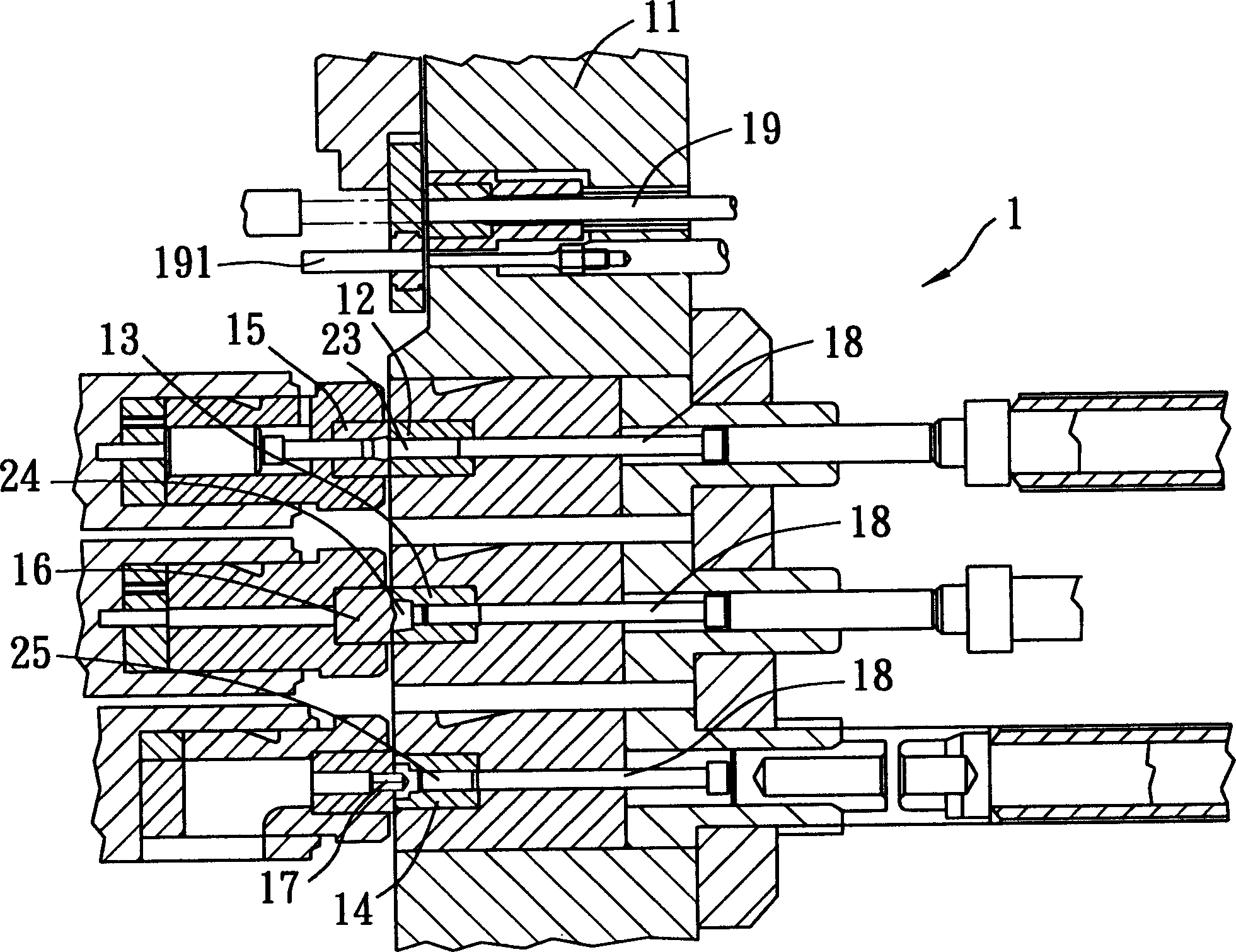
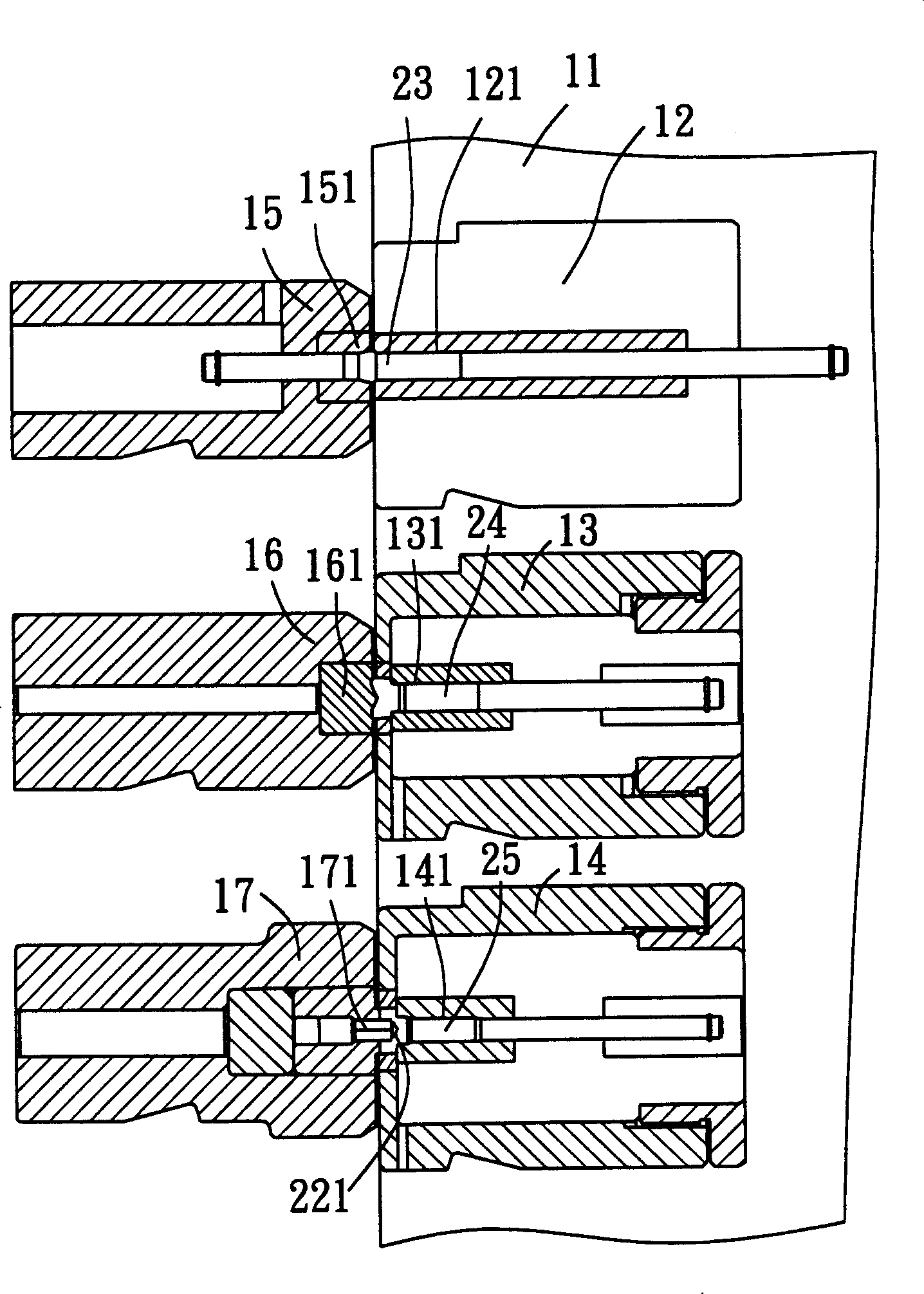
【Technical field】 [0001] The invention relates to a screw manufacturing method and a manufacturing device thereof, in particular to a manufacturing method and a device of a thin hexagonal socket head screw with a wrench guide hole. 【Background technique】 [0002] Such as figure 1 and figure 2 As shown, the conventional screw forming machine 1 has a machine platform 11, a first female mold 12 installed on the machine platform 11, a second female mold 13 and a third female mold 14, and the corresponding positions of the female molds 12-14. The first male mold 15, the second male mold 16, and the third male mold 17, which are forward and can be punched back and forth relative to the female molds 12-14, are located behind the female molds 12-14 and wear correspondingly. The jacking out device 18 extending in the female molds 12-14, and three sets of clamping devices (not shown) that reciprocate synchronously in front of the female molds 12. During manufacture, the wire 19 is...

Claims


Application Information

Patent Timeline
IPC IPC(8): B21K1/46
Inventor 张允得
Owner FUGUANG ENTERPRISE
Why Eureka
Try Eureka