
Polarized element and method for manufacturing same

A polarizing element and polarizing film technology, applied in polarizing elements, optical elements, optics, etc., can solve the problems of loss of polarizing effect of polarizing elements, humidity requirements of polarizing elements, etc., and achieve the effects of not easy damage, high degree of polarization, and long service life.

Inactive Publication Date: 2004-03-17
BEIJING FUNATE INNOVATION TECH +1
View PDF0 Cites 68 Cited by
  • Summary
  • Abstract
  • Description
  • Claims
  • Application Information

AI Technical Summary

Problems solved by technology

Moreover, this type of polarizing element also has high requirements on humidity. Once the working environment is harsh and the humidity is high, the polarizing element will lose its polarizing effect

Method used


Image

  • Polarized element and method for manufacturing same
  • Polarized element and method for manufacturing same
  • Polarized element and method for manufacturing same

Examples


Embodiment Construction

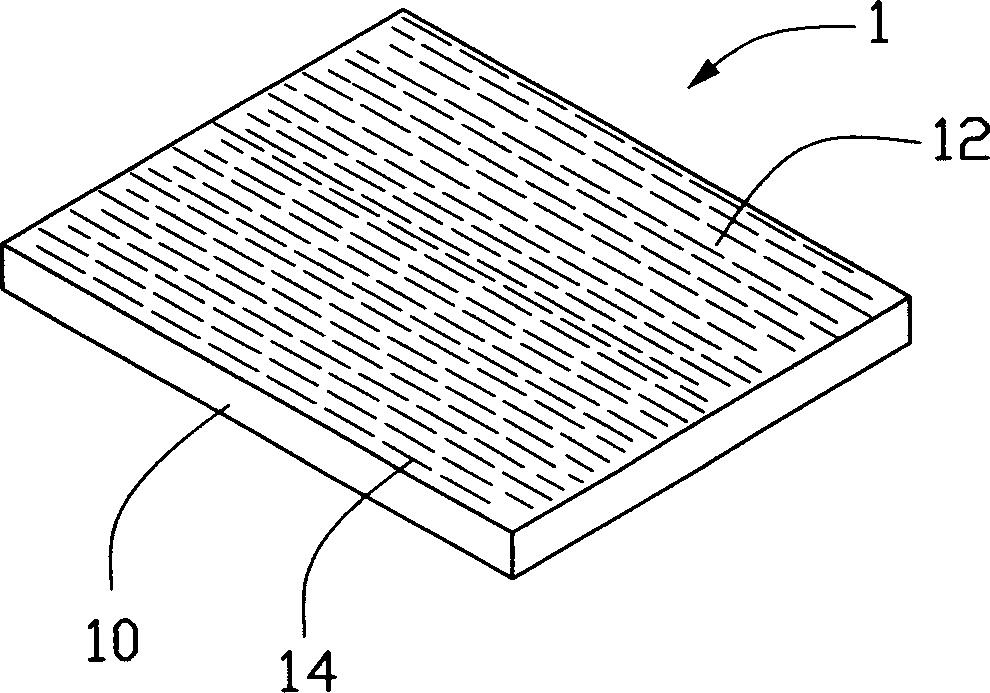
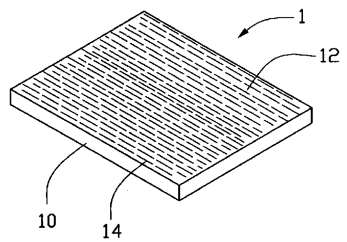
[0022] see figure 1 , the polarizing element 1 of the present invention includes a transparent substrate 10 and a polarizing film 12 distributed on the substrate, and the polarizing film includes a series of carbon nanotubes 14 closely arranged in parallel. Since the carbon nanotubes 14 arranged in parallel have a diameter of 0.4-30 nm, the polarizing element 1 can polarize ultraviolet light and light with a wavelength longer than ultraviolet, and its polarization degree for light in the ultraviolet range can reach 0.92. When the light wave is incident, the light whose vibration direction is parallel to the length direction of the carbon nanotube 14 is absorbed, and the light perpendicular to the length direction of the carbon nanotube 14 can be transmitted, so the transmitted light becomes linearly polarized light.

[0023] To manufacture the above polarizing element 1, the present invention provides the following method:

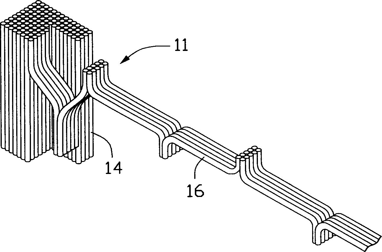
[0024] Firstly, a carbon nanotube array is prepared...


PUM

PropertyMeasurementUnit
diameteraaaaaaaaaa

Abstract

The invention discloses an optical polarized light element and method for manufacturing the same, wherein the method comprises, providing a silicon base having a smooth surface, depositing iron catalyst onto the silicon base surface, feeding the silicon base into a reaction furnace, heating the reaction furnace and feeding in the mixture gas of acetylene and argon, controlling the flow capacity of the mixture gas, controlling the mixture ratio of acetylene and argon gas, gripping and pulling a bundle of carbon nanometer tubes using a clamp, arranging the carbon nanometer tubes rope compactly and parallelly onto a transparent base sheet.

Description

【Technical field】 [0001] The invention relates to an optical device and a manufacturing method thereof, in particular to a polarizing element and a manufacturing method thereof. 【Background technique】 [0002] Polarizer is an important optical device widely used in sunglasses and liquid crystal displays. A polarizing element that is widely used now can absorb light of one polarization state, while light of another polarization state passes through the polarizing element. Such a polarizing element is usually produced by dissolving or absorbing dichroic molecules in a polymer substance, such as polyvinyl alcohol, and stretching the resulting film in one direction to align the dichroic molecules. At this time, the dichroic molecules are regularly arranged along the stretching direction to form long chains. In the incident light wave, the light vibration direction parallel to the long chain direction is absorbed, and the light vibration direction perpendicular to the long chai...

Claims


Application Information

Patent Timeline
Patent Type & Authority Applications(China)
IPC IPC(8): C01B31/02G02B5/30
CPCY10S359/90G02B5/3058G02B5/3075B82Y20/00Y10T428/2918Y10T428/24132Y10T428/30
Inventor 姜开利范守善李群庆
Owner BEIJING FUNATE INNOVATION TECH
Learn More