Electric voltage regulator

A voltage regulator and voltage technology, which is applied in the direction of adjusting electrical variables, control/regulation systems, instruments, etc., can solve problems such as increased current consumption, deterioration of response characteristics, and deterioration of stability

Inactive Publication Date: 2004-04-07
SEIKO INSTR INC
View PDF1 Cites 26 Cited by
  • Summary
  • Abstract
  • Description
  • Claims
  • Application Information

AI Technical Summary

Problems solved by technology

Therefore, there is a problem that the response characteristic deteriorates
In addition, when the response characteristic is improved, the consumption current increases and the stability deteriorates, requiring a large capacitor at the output of V / R

Method used


Image

  • Electric voltage regulator
  • Electric voltage regulator
  • Electric voltage regulator

Examples


Embodiment

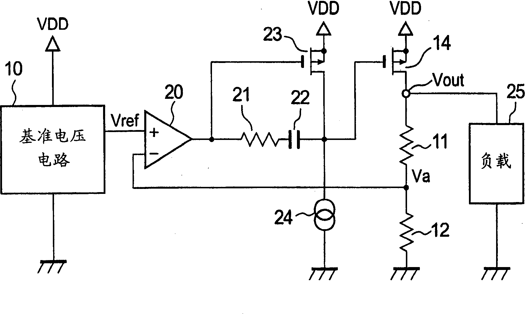
[0020] Embodiments of the present invention will be described below with reference to the accompanying drawings. figure 1 is a V / R circuit diagram showing an embodiment of the present invention. The reference voltage circuit 10, the voltage divider resistors 11 and 12, the output transistor 14, and the load 25 are the same as conventional ones.

[0021] The differential amplifying circuit 20 is a single-stage voltage amplifying circuit, and its output terminal is connected to the gate of the MOS transistor 23 constituting the common source amplifying circuit and the resistor side as one end of the phase compensation circuit composed of the resistor 21 and the capacitor 22 . The transistor 23 is driven by a constant current through a constant current circuit 24 . The output end of the common source amplifier circuit is connected with the other end of the phase compensation circuit and the gate of the output transistor 14 .

[0022] In other words, the error amplifying circuit...


PUM


Abstract

Provided is a voltage regulator which has a high speed response property in a low consumption current and is stably operable in a low output capacitance. The voltage regulator has: a differential amplifier for comparing an output of a reference voltage circuit with an output of a voltage dividing circuit and outputting a first signal; a phase compensating circuit in which a resistor and a capacitor are connected in series; a MOS transistor in which an output of the differential amplifier is inputted to a gate electrode, which is connected between a power supply and the phase compensating circuit, and in which a source is grounded; a constant current circuit connected between the MOS transistor and a ground; and an output transistor in which a second signal output from a connection point between the MOS transistor and the phase compensating circuit is inputted to a gate electrode and which is connected between the power supply and the voltage dividing circuit. A resistor side of the phase compensating circuit is connected with an output terminal of the differential amplifier and a capacitor side of the phase compensating circuit is connected with a drain electrode of the MOS transistor.

Description

technical field [0001] The present invention relates to a voltage regulator (hereinafter referred to as V / R) capable of improving the response performance of the V / R and capable of stably operating with a small output capacitance. Background technique [0002] According to the conventional V / R described in JP04-195613A, the V / R is composed of an error amplifier with a single-stage voltage amplification. In other words, a conventional V / R has a circuit as shown in FIG. 5 . The composition of V / R is: an error amplifier 13 and an output transistor 14; the error amplifier 13 is used to amplify the reference voltage of the reference voltage circuit 10 and divider resistors 11 and 12 for dividing the output voltage Vout of V / R The differential voltage between the voltages at the connection point. When the output voltage of the error amplifier 13 is expressed as Verr, the output voltage of the reference voltage circuit 10 is expressed as Vref, and the voltage at the connection po...

Claims


Application Information

Patent Timeline
Patent Type & Authority Applications(China)
IPC IPC(8): G05F1/56G05F1/575H03F3/345
CPCG05F1/575G05F1/56
Inventor 须藤稔加纳贤次
Owner SEIKO INSTR INC
Why Eureka
Try Eureka