Time-delay locking loop circuit for internally correcting dutyratio and method for correcting duty cycle thereof

A technology of delay-locked loop and duty cycle, which is applied to electrical components, automatic control of power, angle demodulation through phase difference detection, etc., can solve problems such as abnormal operation, increased power consumption, and limited operating frequency

Inactive Publication Date: 2004-04-07
SAMSUNG ELECTRONICS CO LTD
View PDF1 Cites 21 Cited by
  • Summary
  • Abstract
  • Description
  • Claims
  • Application Information

AI Technical Summary

Problems solved by technology

[0009] However, the duty ratio correction method using the phase mixer 20 has the following defects: First, the range of DCC is related to the slope of the signals IN1 and IN2
If the duty cycle of an external clock signal ECLK has a ratio of 40 to 60 or 60 to 40, the DCC may not work properly and at the same time the power consumption increases, which limits the operating frequency

Method used


Image

  • Time-delay locking loop circuit for internally correcting dutyratio and method for correcting duty cycle thereof
  • Time-delay locking loop circuit for internally correcting dutyratio and method for correcting duty cycle thereof
  • Time-delay locking loop circuit for internally correcting dutyratio and method for correcting duty cycle thereof

Examples


Embodiment Construction

[0035] The accompanying drawings show preferred embodiments of the invention, and the invention will be more fully described below with reference to the accompanying drawings.

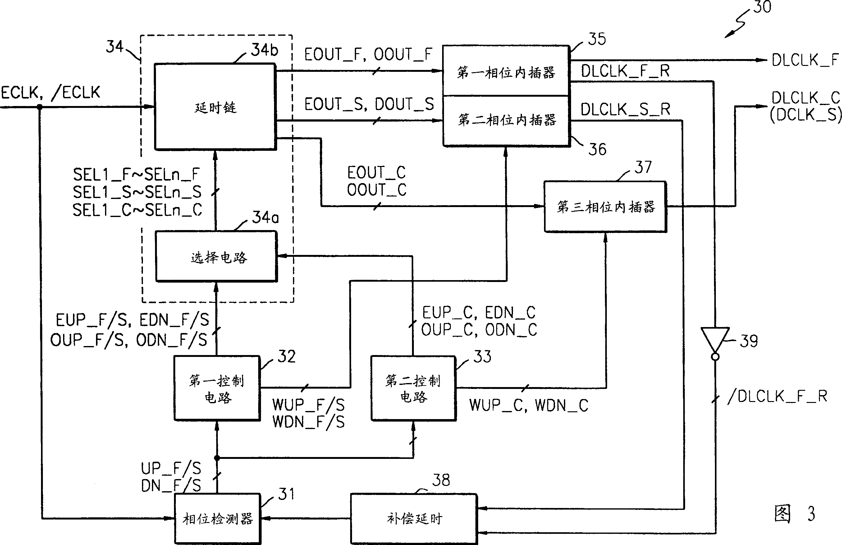
[0036] FIG. 3 is a block diagram of a DLL 30 with a duty cycle corrector (DCC) according to an embodiment of the present invention.

[0037] Referring to Fig. 3, DLL30 comprises phase detector 31, first control circuit 32, second control circuit 33, delay line unit 34, first phase interpolator 35, second phase interpolator 36, third phase interpolator device 37 and compensation delay 38.

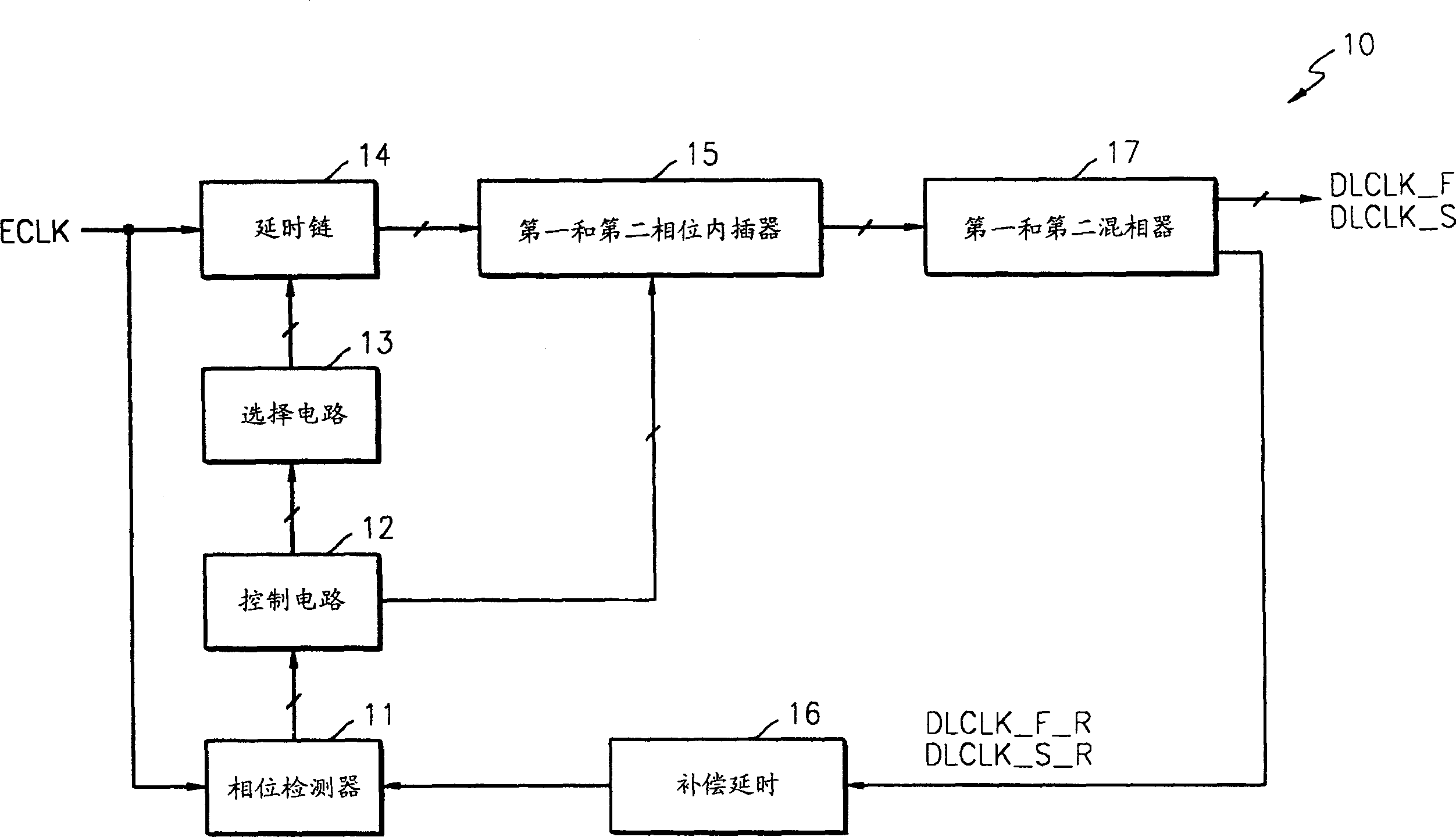
[0038] DLL 30 is capable of correcting the duty cycle. A traditional DLL for double data rate (DDR) systems contains two loops to control the rising and falling edges and a phase mixer to correct the duty cycle. Instead, another loop is included in the DLL 30 to modify the duty cycle instead of the phase mixer. That is, in figure 1 In the conventional DLL shown, the second control circuit 33 and the third phase i...


PUM


Abstract

A delay locked loop (DLL) circuit having a duty cycle corrector (DCC) that has a broad range of duty cycle correction, consumes only a small amount of power, has few restrictions on operating frequency, and improves the characteristics of a memory device is described. The delay locked loop circuit includes an additional loop for duty cycle correction as well as loops for controlling a rising edge and a falling edge of output signals. Thus, the delay locked loop circuit can internally correct the duty cycle without the use of a phase blender.

Description

[0001] This application claims priority from Korean Patent Application Serial No. 2002-60814 filed with the Korean Intellectual Property Office on October 5, 2002, the disclosure of which is hereby incorporated by reference in its entirety. technical field [0002] The invention relates to a delay locked loop (Delay Locked Loop, DLL) circuit, in particular to a DLL for internally modifying the duty cycle and a method for modifying the duty cycle. Background technique [0003] In data transmission between, for example, a memory device and a memory controller, by synchronizing the data with a clock signal before sending the data, the bus load and the transmission frequency increase. Therefore, it is increasingly important to synchronize data with a clock signal. That is, the time required to load data onto the bus in response to a clock signal is compensated to place the data on the edge or center of the clock signal. Between a phase locked loop (PhaseLocked Loop, PLL) circui...

Claims


Application Information

Patent Timeline
Patent Type & Authority Applications(China)
IPC IPC(8): G06F1/04G11C11/407G11C11/4076H03D3/24H03K5/04H03K5/13H03K5/156H03L7/06H03L7/08H03L7/081H03L7/089H04L7/033
CPCH03K5/1565H03L7/0814H03L7/089H03K5/13H03L7/0818H03L7/0816H03L7/08
Inventor 赵根熙金圭现
Owner SAMSUNG ELECTRONICS CO LTD
Why Eureka
Try Eureka