Coaxile reverse rotating type radio controlled vertiplane

A helicopter, inversion technology, applied in the direction of rotorcraft, aircraft, motor vehicles, etc., can solve the problems of poor maintenance performance and movement performance, complex mechanism, reduce the maximum size of the fuselage, etc., and achieve the rotor drive and control mechanism. simple effect

Inactive Publication Date: 2004-05-19
HIROBO
View PDF1 Cites 24 Cited by
  • Summary
  • Abstract
  • Description
  • Claims
  • Application Information

AI Technical Summary

Problems solved by technology

[0005] The coaxial counter-rotating helicopter utilizes the above-mentioned structure. Since the tail propeller is not required, the maximum size of the fuselage can be reduced. The rotation of the rotor is all based on buoyancy, so the efficiency is high, and it can hover in a completely horizontal state, and the left and right rudders rotate. There are many advantages such as smoothness, but conversely, because the upper and lower rotors that rotate in opposite directions are arranged coaxially, the mechanism for driving and controlling the rotors becomes complicated, and the maintenance performance and motion performance are inferior to those of single-rotor helicopters. And other issues
Therefore, there are very few examples of adoption on R / C helicopters on actual machines

Method used


Image

  • Coaxile reverse rotating type radio controlled vertiplane
  • Coaxile reverse rotating type radio controlled vertiplane
  • Coaxile reverse rotating type radio controlled vertiplane

Examples


Embodiment Construction

[0024] Preferred embodiments of the present invention will be described below with reference to the accompanying drawings.

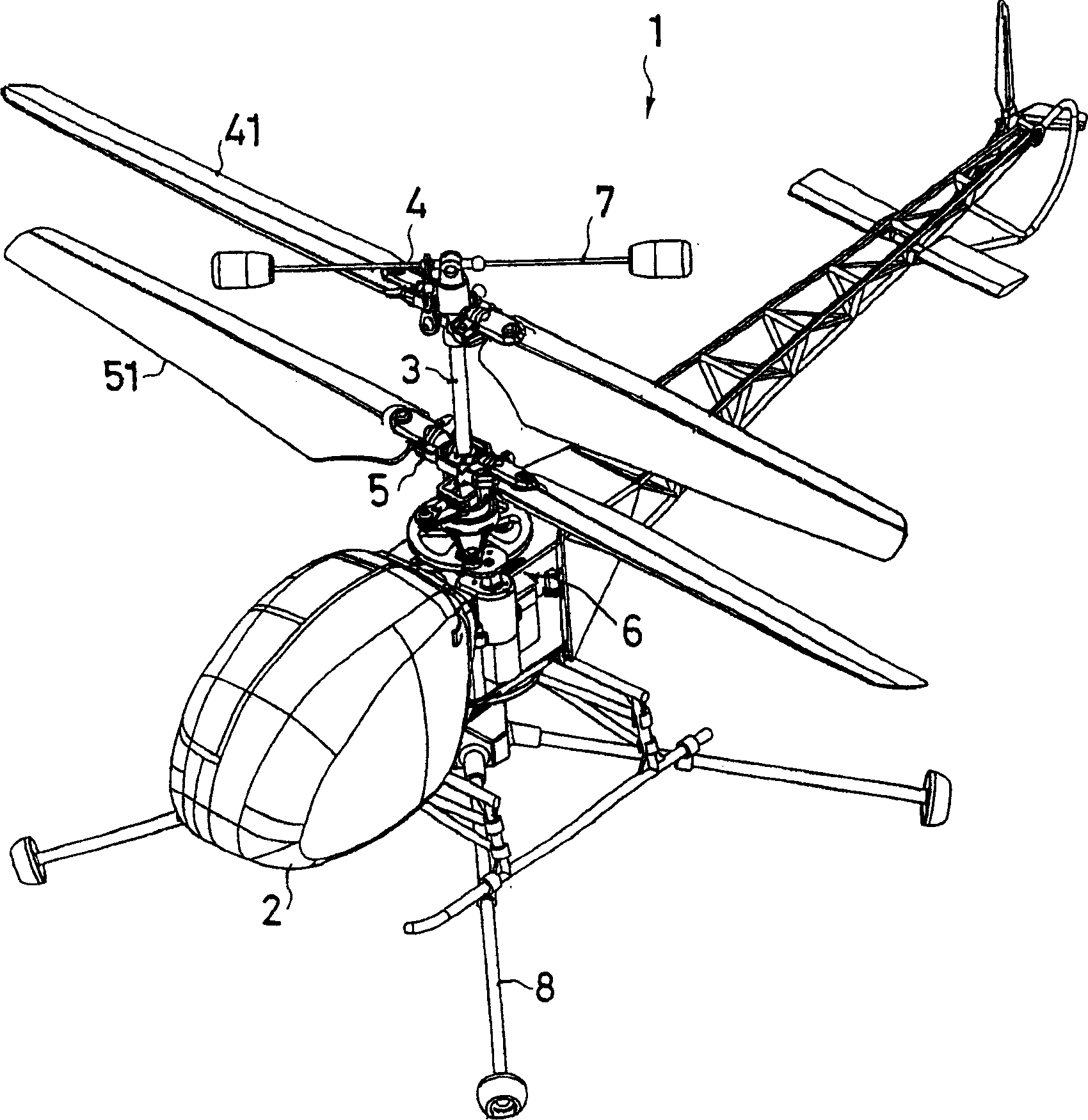
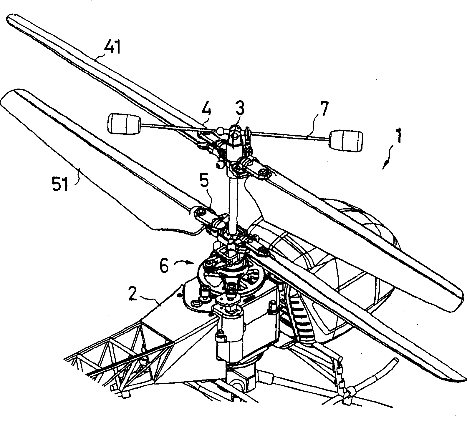
[0025] figure 1 It is the appearance of an R / C helicopter of an embodiment of the present invention seen from obliquely forward, figure 2 Indicates the appearance of the main parts seen from the oblique rear. In the figure, the number 1 is the R / C helicopter, 2 is the fuselage, 3 is the column, 4 is the upper rotor head, 5 is the lower rotor head, 6 Is a wing tilting mechanism, 7 is a stabilizer, and 8 is a foot that can be freely disassembled and installed on the bottom of the fuselage to prevent overturning.

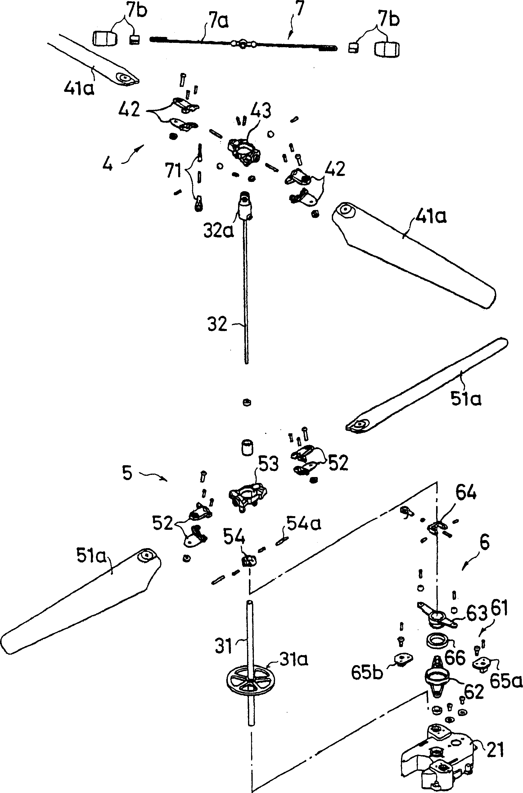
[0026] Such as image 3 As shown, the column 3 is composed of a hollow outer shaft column 31 protruding upward from the inside of the fuselage 2 and a hollow inner shaft column 32 passing through the interior thereof. The lower part of the outer column 31 is connected to the drive shaft of a lower rotor motor (not shown) provided inside the f...


PUM


Abstract

To provide a coaxial contrarotating radio controlled (R/C) helicopter having maneuverability and operationality sufficient for enjoying manipulating the R/C helicopter indoors by constituting a simple mechanism for driving and controlling rotors. This coaxial contrarotating R/C helicopter is equipped with a swash plate comprising a lower plate, mounted to move around the rotary axis of a mast in a direction to intersect the rotary axis by a geared motor, and an upper plate which is mounted on the central opening part of the lower plate through a bearing and is connected with the lower plate through a blade holder and a control arm slantingly connected to the mast. The rotational surfaces of the lower blades is tilted by the control arm in conjunction with the movement of the swash plate in the direction to intersect the rotary axis of the mast. As a result, a moving direction of the aircraft is controlled. The flight posture of the aircraft is controlled by interlocking rotations made by an upper rotor head and a stabilizer. (C)2004,JPO.

Description

【Technical field】 [0001] The present invention relates to a coaxial reversible radio control helicopter (hereinafter referred to as an R / C helicopter) in which upper and lower rotor heads rotating in opposite directions are coaxially arranged. 【Background technique】 [0002] Generally, the structure of the coaxial inverted helicopter is that the upper rotor head and the lower rotor head are coaxially arranged on the fuselage, and by making the upper and lower rotors rotate in opposite directions, the generation of lift force and the torque offset. In addition, by changing the direction control of the nose by changing the tail propeller, by making the helix angles of the upper and lower rotors change in opposite directions through the corresponding swash plates respectively, under the condition of keeping the total lift force constant, the torque will be destroyed. balanced (for example, refer to Patent Document 1). [0003] Patent Document 1 [0004] Japanese Patent Appli...

Claims


Application Information

Patent Timeline
Patent Type & Authority Applications(China)
IPC IPC(8): B64C27/10B64C27/54B64C27/82
Inventor 松坂敬太郎中村公勇
Owner HIROBO
Why Eureka
Try Eureka