Water treatment unit

A technology of water treatment device and electrolytic treatment, which is applied in the direction of water supply device, water/sewage treatment, water/sewage treatment equipment, etc., can solve the problems of increased operating cost and time-consuming, and achieve the effect of eliminating the fault of abnormal current

Active Publication Date: 2004-05-26
SANYO ELECTRIC CO LTD
View PDF0 Cites 8 Cited by
  • Summary
  • Abstract
  • Description
  • Claims
  • Application Information

AI Technical Summary

Problems solved by technology

[0006] However, the methods and devices disclosed in the above documents have the problem of periodically replenishing the chlorine supplier with an irritating chlorine agent such as an aqueous solution of sodium hypochlorite, which takes time and effort and increases operating costs.

Method used


Image

  • Water treatment unit
  • Water treatment unit
  • Water treatment unit

Examples


Embodiment Construction

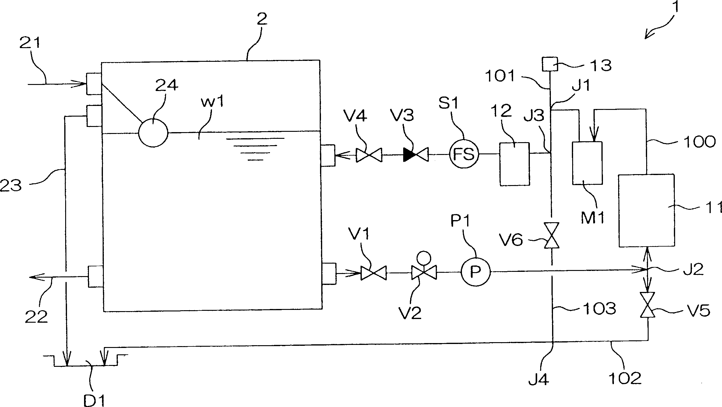
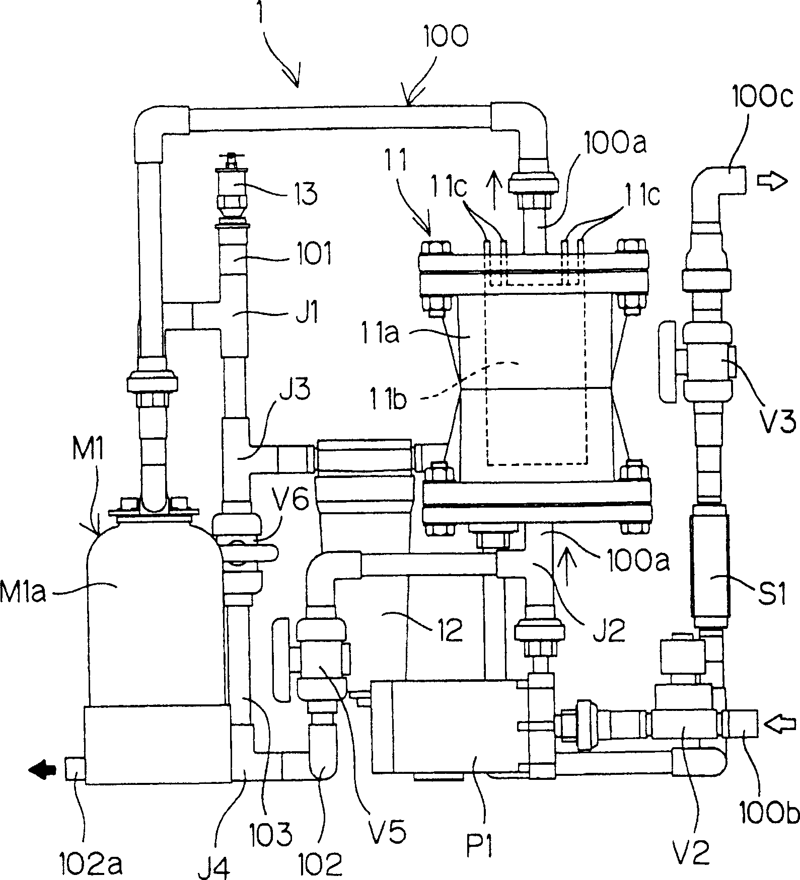
[0079] figure 1 In order to show in a simplified manner, a water treatment device 1 according to an embodiment of the present invention is connected to a water supply tank 2 for drinking water installed on the roof of a building, an apartment, etc. Diagram of the structure used within the purification. in addition, figure 2 It is a front view of the physical pipe in the above-mentioned water treatment device 1 .

[0080] Referring to these drawings, the water treatment device 1 of this example has a treatment water circuit 100 for obtaining water w1 from the water supply tank 2, performing electrolytic treatment on it through the electrolytic treatment mechanism 11, and then returning it to the water supply tank 2 again. Water supply tank 2.

[0081] exist figure 1 Among them, reference numeral 21 denotes a pipe for supplying water from a water supply source such as a water pipe to the water supply tank 2, and reference numeral 22 denotes a pipe for supplying water from t...


PUM


Abstract

Provided is a water treatment equipment which sterilizes water fed from a water supply inlet of a water supply system in a building etc. efficiently by electrolysis treatment to keep the water quality while keeping the airtightness of a water supply tank and preventing a gas storage problem.An automatic gas vent valve 13 for discharging a gas generated by the electrolysis treatment to the outside of a treated water passage 100 is connected onto the downstream side from an electrolysis treatment mean 11 of the treated water passage 100 connected with a water supply tank 2, and a function for accelerating the inflow of gas into the automatic gas vent valve 13 by stopping operation for a while is given. The gas generated by the electrolysis treatment can be collected in the automatic gas vent valve 13 by buoyancy of the gas during temporary stopping of the apparatus, and discharged outside of the treated water passage 100, which can surely prevent the gas from being stored in the water supply tank 2 while keeping the airtightness of the water supply tank 2.

Description

technical field [0001] The present invention relates to a water treatment device for sterilizing water stored in, for example, a water supply tank installed on the roof of a building, or various water tanks such as pools and bathtubs. Background technique [0002] For example, in buildings such as office buildings and apartments, water supply channels are generally provided as water supply facilities for supplying water to multiple water supply outlets (water supply faucets, water supply parts of water heaters, etc.) installed on each floor. Water taken from a water pipe is temporarily stored in a water supply tank installed on the roof of a building, and then supplied from the water supply tank to each water supply port. [0003] In the above-mentioned water supply facilities, maintaining the quality of water has traditionally depended on the sterilizing power of chlorine added to tap water in a tap water treatment plant. [0004] However, in many cases, regular maintenanc...

Claims


Application Information

Patent Timeline
Patent Type & Authority Applications(China)
IPC IPC(8): E03B11/12C02F1/46C02F1/467
CPCC02F1/467C02F2201/4614C02F2201/46145
Inventor 稻本吉宏广田达哉杉本宗明河村要藏岸稔
Owner SANYO ELECTRIC CO LTD
Why Eureka
Try Eureka