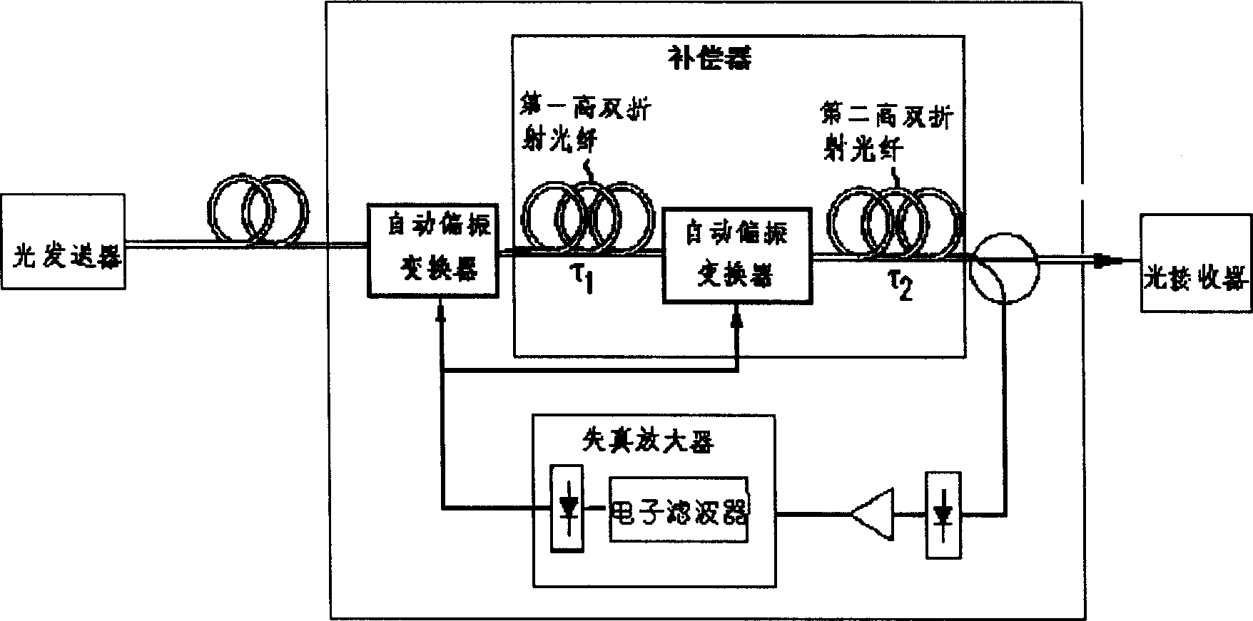
Variable birefringence cell and dispersion compensator in polarization mode

A polarization mode dispersion and birefringence technology, applied in instruments, electrical components, electromagnetic wave transmission systems, etc., can solve problems such as signal distortion and deformation, increase bit error rate, etc., to reduce difficulty and cost, adjust speed, and compensate accuracy. high effect

Inactive Publication Date: 2004-05-26
HUAWEI TECH CO LTD
View PDF1 Cites 6 Cited by
  • Summary
  • Abstract
  • Description
  • Claims
  • Application Information

AI Technical Summary

Problems solved by technology

Polarization mode dispersion will cause pulse broadening and increase the bit error rate in digital communication s

Method used


Image

  • Variable birefringence cell and dispersion compensator in polarization mode
  • Variable birefringence cell and dispersion compensator in polarization mode
  • Variable birefringence cell and dispersion compensator in polarization mode

Examples


Example Embodiment

[0052] refer to Figure 5 ,from Figure 5 It can be seen that the structure of the PMD compensator of the present invention includes the following four parts: 1, polarization controller; 2, variable birefringence unit; 3, DOP (degree of polarization) monitoring unit; 4, central control unit. As far as the feedback control structure adopted in the present invention is concerned, as we introduced earlier, it is a structure commonly used in the industry, and the second part (ie, the variable birefringence unit) is the core content of the present invention.

[0053] The variable birefringence unit mainly includes a chirped fiber grating (ie chirp FBG) and a pressure generating device, wherein the chirped fiber grating is located in the extrusion direction of the pressure extrusion device. In addition, the variable birefringence unit also includes a three-port optical circulator (Opticalcirculator), wherein the first port of the three-port optical circulator is connected with the ...


PUM


Abstract

The invention relates to variable birefringence unit and PMD compensator using the said unit. The variable birefringence unit includes chatter optical fiber grating and pressure generation unit. The said grating is on direction of extrusion of the pressure generation unit. A dispersion compensator in polarization mode includes a polarisation controller, detector for testing degree of polarization and central control unit. The polarisation controller receives incident light and adjusts polarized state of light signal. The dispersion compensator in polarization mode also includes the variable birefringence unit. The invention realizes birefringence being adjustable continuously so as to realize difference of group delay between polarization states being adjustable continuously.

Description

technical field [0001] The present invention relates to a variable birefringence unit and its polarization-mode dispersion compensator, in particular to a unit in an optical communication system that uses stress to change the refractive index of a linear chirped grating and a polarization-mode dispersion compensator using the variable birefringence unit . Background technique [0002] PMD (polarization mode dispersion, polarization mode dispersion) refers to two mutually orthogonal polarization modes LP transmitted in a single-mode fiber 01 X and LP 01 Y , the arrival time difference after a certain distance transmission in the optical fiber. The unit of measure for PMD is Ps. In the ideal case where the optical fiber is collimated, the cross-section is standard circular, and the refractive index distribution is uniform, symmetrical and isotropic everywhere, LP 01 X and LP 01 Y The transmission constants βx and βy are equal, and the two polarization modes are comple...

Claims


Application Information

Patent Timeline
IPC IPC(8): G02B6/34G02F1/03
Inventor 刘仲恒
Owner HUAWEI TECH CO LTD
Why Eureka
Try Eureka