Substrate calibrating appts, its processing device and delivery appts.

A technology for calibrating devices and substrates, applied in optics, instruments, opto-mechanical equipment, etc., can solve problems such as generation of debris and scratches, and achieve the effect of saving consumption

Inactive Publication Date: 2004-05-26
TOKYO ELECTRON LTD
View PDF3 Cites 35 Cited by
  • Summary
  • Abstract
  • Description
  • Claims
  • Application Information

AI Technical Summary

Problems solved by technology

In the case of such a large substrate, with the alignment mechanism of the prior art, there is a possibility that even if the side of the substrate is pushed with a jig, the substrate

Method used


Image

  • Substrate calibrating appts, its processing device and delivery appts.
  • Substrate calibrating appts, its processing device and delivery appts.
  • Substrate calibrating appts, its processing device and delivery appts.

Examples


Embodiment Construction

[0040] Preferred embodiments of the present invention will be described below with reference to the drawings.

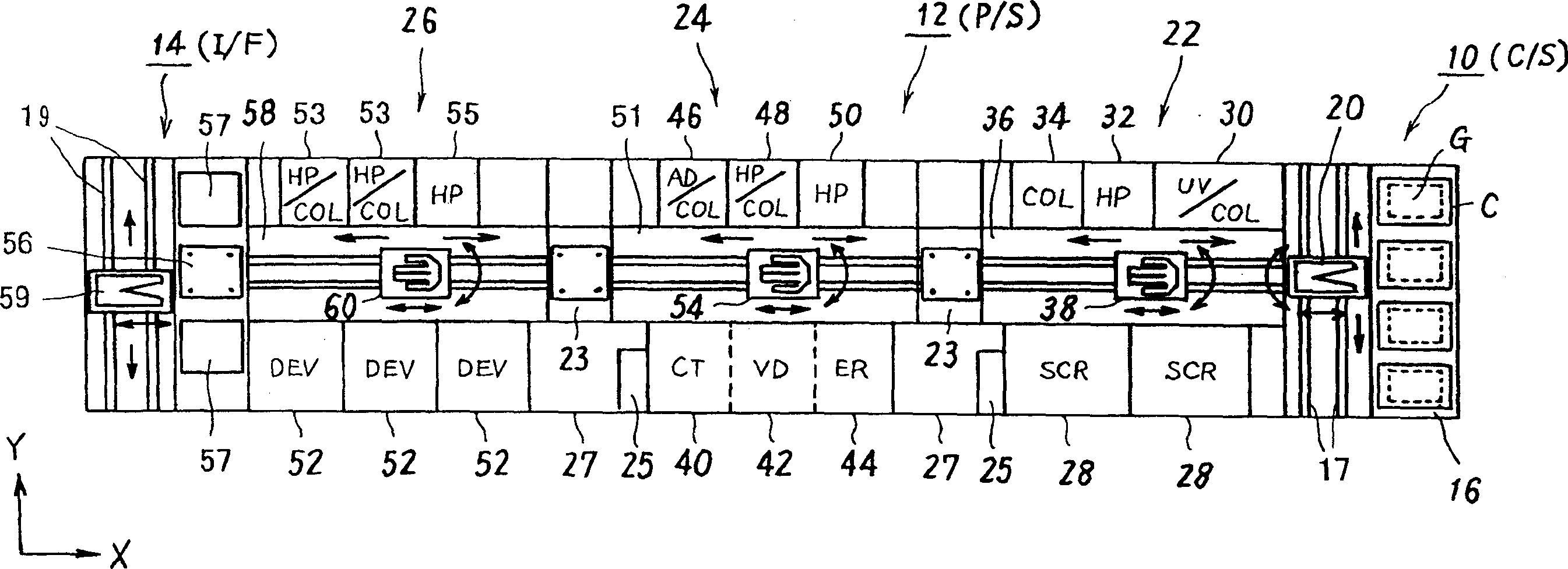
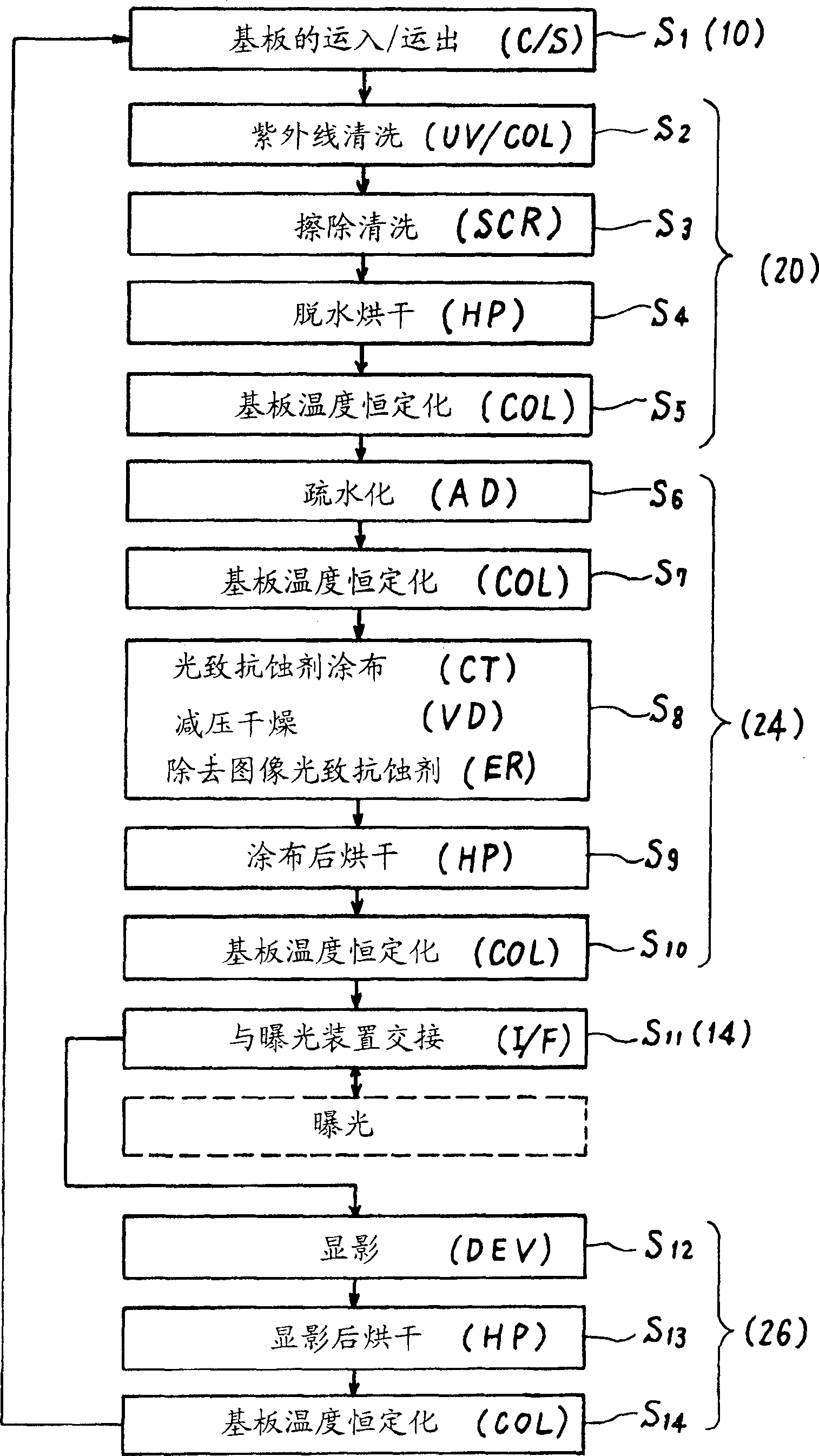
[0041] figure 1A coating and development processing system is shown as a configuration example of a substrate alignment device, a substrate processing device, and a substrate transfer device to which the present invention can be applied. The coating and development processing system is set in a clean room, for example, the LCD substrate is used as the substrate to be processed. During the LCD manufacturing process, cleaning in the photolithography process, coating of photoresist, pre-drying, developing And post-drying and other treatments. Exposure processing is performed with an external exposure device (not shown in the figure) provided adjacent to the system.

[0042] The coating and development processing system is roughly divided into a substrate box station (C / S) 10, a processing station (P / S) 12, and an interface unit (I / F).

[0043] The substrate cassette...


PUM


Abstract

By ejecting a high-pressure gas, supplied from a high-pressure gas supply source, from a gas-ejecting part 116 via a gas supply pipe 118 and a vent line 114a inside a cylindrical support 114 at a prescribed pressure, namely a pressure that cancels the gravity of the substrate G or a pressure which exceeds the same, when the substrate G is loaded on a stage 100, the substrate G substantially floats from support pins 108. Since the gas-ejecting part 116 is formed into a horn shape, air which hits the lower face of the substrate G smoothly passes to the outside through a gap g without producing vortices.

Description

technical field [0001] The present invention relates to a substrate alignment device, a substrate processing device, and a substrate transfer device used in manufacturing processes such as liquid crystal displays (LCDs), and particularly relates to a technique for mechanically aligning substrates to be processed. Background technique [0002] Traditionally, in the LCD manufacturing process, in order to align the processed substrate (glass substrate) on the workbench along the XY direction before processing or during transportation, one side is used to support the substrate substantially horizontally at a predetermined distance. On a plurality of support pins arranged at intervals on the workbench, a mechanical alignment mechanism that pushes the corners of the substrate or the side surfaces of each side in a predetermined direction with an appropriate jig (for example, refer to Japanese Patent Laid-Open No. 2001-44118 Bulletin figure 2 And explanation based on this figure, ...

Claims


Application Information

Patent Timeline
IPC IPC(8): H01L21/027G02F1/133G03F7/00G03F9/00
CPCG02F1/1303H01L21/67742H01L21/68
Inventor 立山清久元田公男岩崎达也
Owner TOKYO ELECTRON LTD
Why Eureka
Try Eureka