Multiple wavelength coding optical switch array

A technology of switching arrays and coded light, which is applied in the field of optical communication, can solve the problems of complex equipment, large loss, and slow transmission speed, and achieve the effects of reducing system cost, long working life, and reducing optical loss

Inactive Publication Date: 2004-06-02
SHANGHAI INST OF LASER TECH
View PDF0 Cites 2 Cited by
  • Summary
  • Abstract
  • Description
  • Claims
  • Application Information

AI Technical Summary

Problems solved by technology

[0002] In terms of information technology, more and more information shows that after the Internet, one of the largest industries in information is photonics, which uses optical methods to carry out the Internet, with fast speed and large capacity, and replaces routers in the switching network with optical fiber devices. The interconnection of the Golden Optical Network can be realized. However, the current use of optical devices to replace the routers in the switching network still has the disadvantage of the so-called "electronic bottleneck". After the electronic cross-connection, re-realize the optical / electrical conversion and enter the optical transmission network, not only the equipment is complex, the transmission speed is slow, and the loss is large

Method used


Image

  • Multiple wavelength coding optical switch array
  • Multiple wavelength coding optical switch array

Examples


Embodiment Construction

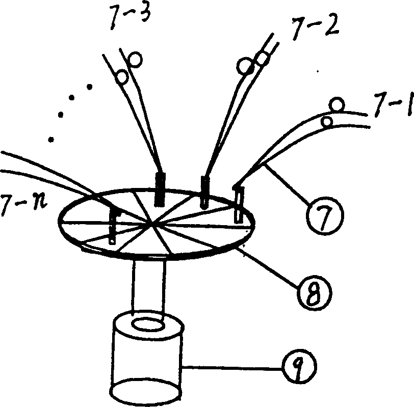
[0012] Please refer to the attached figure 1 As shown, the reflective surface coded optical switch array is composed of reflective medium film thin disks 8 driven by m double-hole collimators 7 and ultra-small inertia electromagnetic rotating shafts 9 to form a reflective surface coded optical switch. The reflective medium film is based on the mathematical model Coating in the public area, the double-hole collimator is arranged according to the computer addressing program, and is fixed above the reflective medium film. There is a very small air gap between the double-hole collimator and the reflective medium film, and the ultra-small inertia shaft drives the reflective medium film The turntable rotates at a high speed. When the reflective area of ​​the coating is parallel to the corresponding end face of the collimator, the optical signals at the input and output ends of the collimator are connected. On the contrary, when the non-reflective area is parallel to the collimator, t...


PUM


Abstract

Several optical fibers and an optical wave separator constitute n independent light paths of different wavelengths, and the n independent light paths are arranged into an array via two-aperture fiber collimator. The encoding switch has one coaxial rotor of light scanner to drive one zoned encoding holoreflecting medium diaphragm, and the reflecting areas correspond to the two-aperture fiber collimator. When the reflecting areas align the end of the two-aperture fiber collimator parallelly, the two-aperture fiber collimator forms a optical path, or else, no optical path is formed. The light crossed connection is realized by means of encoding of double fiber array and reflecting areas.

Description

technical field [0001] A multi-wavelength coded optical switch array belongs to the technical field of optical communication. Background technique [0002] In terms of information technology, more and more information shows that after the Internet, one of the largest industries in information is photonics, which uses optical methods to carry out the Internet, with fast speed and large capacity, and replaces routers in the switching network with optical fiber devices. The interconnection of the Golden Optical Network can be realized. However, the current use of optical devices to replace the routers in the switching network still has the disadvantage of the so-called "electronic bottleneck". After the electronic cross-connection, re-realize the optical / electrical conversion and enter the optical transmission network, not only the equipment is complex, the transmission speed is slow, and the loss is large. Contents of the invention [0003] In order to solve the so-called "...

Claims


Application Information

Patent Timeline
Patent Type & Authority Applications(China)
IPC IPC(8): G02B6/35
Inventor 王又良王海彪曲世浦
Owner SHANGHAI INST OF LASER TECH
Why Eureka
Try Eureka