
Fault current-limiting device for transmission and distribution electric network

A fault current limiter and fault current limiting technology, applied in power network operating system integration, electrical components, circuit devices, etc., can solve the problems of long interruption time, poor reliability, and inability to limit steady-state fault current, and achieve reliable The effect of cutting off fault current and reducing impact

Inactive Publication Date: 2004-06-30
INST OF ELECTRICAL ENG CHINESE ACAD OF SCI
View PDF1 Cites 1 Cited by
  • Summary
  • Abstract
  • Description
  • Claims
  • Application Information

AI Technical Summary

Problems solved by technology

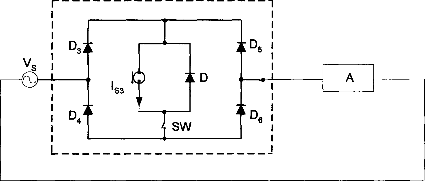
Since the short-circuit protection circuit is rectified, the current flows through the equivalent current source, that is, the inductor in a single phase, which makes the inductor current be charged before the fault is removed, so the capacity of the inductor is very large, and with the increase of the inductor current, the inductor is charged. The time in series with the voltage source circuit is getting shorter and shorter, which makes the current limiting effect worse and worse until the current limiting effect is lost, that is, this protection circuit cannot limit the steady-state fault current
Moreover, if it is used in the transmission and distribution network, the short-circuit protection switch SW, whether it is an electronic switch or an electrical switch, the former has a very large capacity, and it needs to break off the fault current with a very large current change rate, and the reliability is poor during the breaking period; if it is the latter, The breaking time is too long, the current limiting effect is poor, and the breaking capacity of the electrical switch is also a big problem due to the gradual increase of the fault current

Method used


Image

  • Fault current-limiting device for transmission and distribution electric network
  • Fault current-limiting device for transmission and distribution electric network
  • Fault current-limiting device for transmission and distribution electric network

Examples


Embodiment Construction

[0016] The present invention will be further described below in conjunction with accompanying drawing and embodiment;

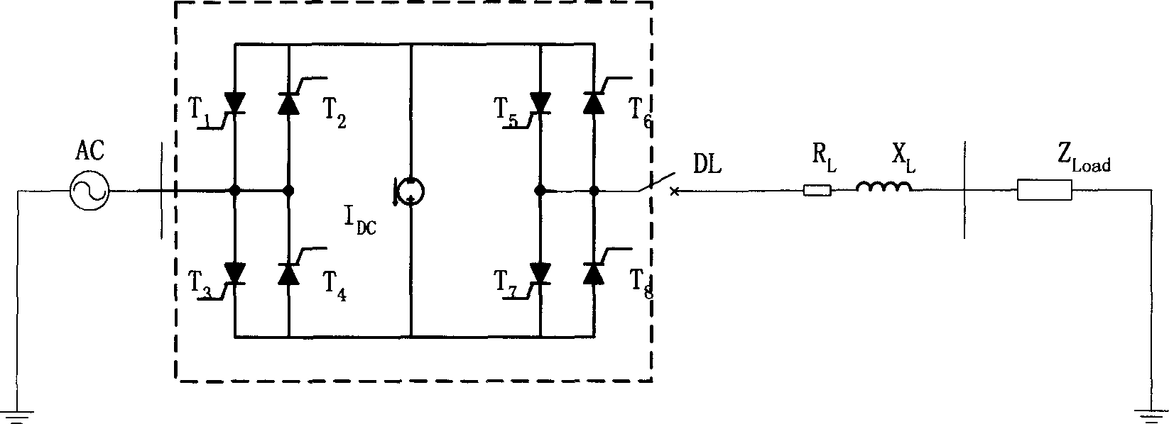
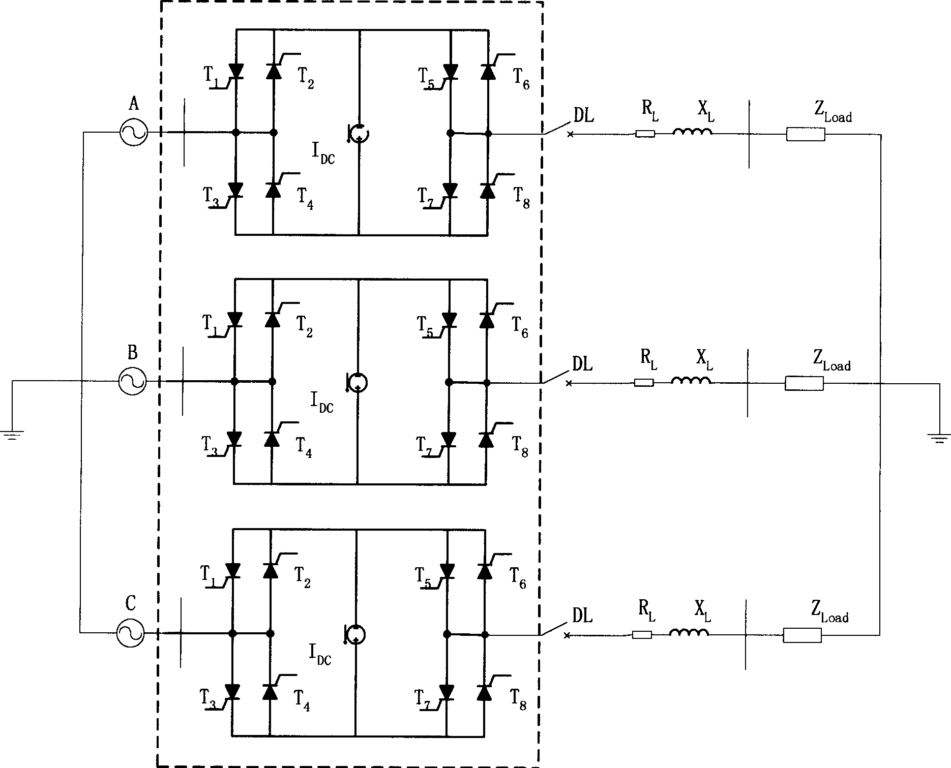
[0017] The present invention as figure 2 , image 3 Shown in the dotted box. exist figure 2 In a single-phase system, the present invention is connected to the outlet of the AC line of the system and connected in series with the circuit breaker DL. It consists of four pairs of thyristors T 1 , T 2 ,T 3 , T 4 ,T 5 , T 6 ,T 7 , T 8 After being connected in series with equivalent current source I DC composed in parallel. exist image 3 In the three-phase system, the present invention is respectively connected to the outlets of the three-phase A, B and C lines in series with the circuit breaker DL, and the three phases are respectively composed of four pairs of thyristors T 1 , T 2 ,T 3 , T 4 ,T 5 , T 6 ,T 7 , T 8 After being connected in series with equivalent current source I DC composed in parallel. figure 2 , image 3 Middle R L 、X...


PUM


Abstract

The circuit is installed at line outlet of electric power system and cascaded to a breaker. The circuit comprises four pair of controlled silicons paralleled in positive and negative direction and cascaded pairwise. The said circuit of silicons is connected to an equivalent current source in parallel. The invention possesses features of high efficiency, simple structure, reliable, solves too large failure current of electric system as well as lowers current tolerance for requiring each electric component, and design specification of system. The circuit raises stability, safety and reliability if it is utilized in high voltage or supervoltage transmission.

Description

Technical field: [0001] The invention relates to a fault current limiter for transmission and distribution network, which belongs to the technical field of electric engineering. Background technique: [0002] Due to the development of the power system, the increase of load, the investment of large-capacity units, power plants and substation equipment, especially the emergence of large power plants in the load center and the interconnection of large power systems, the capacity of the transmission and distribution network has been greatly increased, and at the same time, the short-circuit The current level is increasing day by day, and even the short-circuit current level in some places has exceeded the breaking capacity of the current circuit breaker. If no restrictive measures are taken to control it, not only will the equipment investment of the new substation be greatly increased, but it will also have a great impact on the original substation equipment in the system, and ...

Claims


Application Information

Patent Timeline
Patent Type & Authority Applications(China)
IPC IPC(8): H02J3/00H02J9/02
CPCY02B70/30Y04S20/20
Inventor 赵彩宏肖立业林良真
Owner INST OF ELECTRICAL ENG CHINESE ACAD OF SCI
Learn More