Ceramic tile forming equipment and forming method

A molding equipment and molding method technology, applied in the direction of ceramic molding machines, molding conveyors, manufacturing tools, etc., can solve the problems of unmaintainable body shape, unguaranteed uniformity and quality, deformation or falling off, etc., to achieve equipment Strong versatility, simple and practical process, and convenient operation

Inactive Publication Date: 2004-07-14
佛山市灵海陶瓷科技有限公司
View PDF0 Cites 12 Cited by
  • Summary
  • Abstract
  • Description
  • Claims
  • Application Information

AI Technical Summary

Problems solved by technology

Since the elastic surround 19 is an elastic body, it is only suitable for producing ceramic tiles with a thickness of 3 to 5 mm. For ceramic tiles with a thickness greater than 8 mm, the lateral thrust increases during the molding p

Method used


Image

  • Ceramic tile forming equipment and forming method
  • Ceramic tile forming equipment and forming method
  • Ceramic tile forming equipment and forming method

Examples


Embodiment Construction

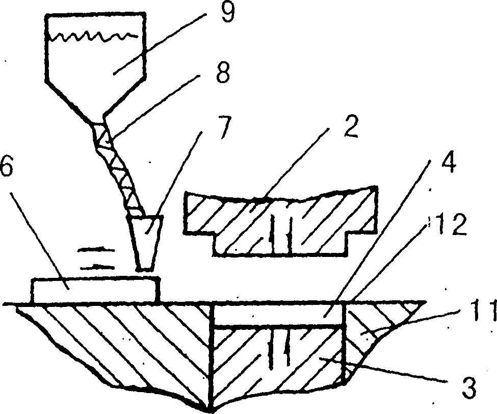
[0037] The features and spirit of the present invention can be more clearly understood through the detailed description of the preferred embodiments in conjunction with the accompanying drawings. Such as Figure 4 As shown, it is a schematic cross-sectional view of a ceramic tile forming equipment according to an embodiment of the present invention. In addition to the known feeding device and the decoration equipment for decorating the brick body, the decoration equipment can be equipment such as cloth or dry powder printing. The outer surface of the upper punch 2 is provided with a sliding mold frame 14 that cooperates with it and can slide axially along the upper punch 2. It is a rigid material. In this embodiment, it is a cast iron material that tightly seals the powder. In its frame, it is movably connected with upper punch 2 by pin body 28 (as Figure 8 ). The pin body 28 can be directly fastened on the inside of the sliding formwork, and its other end is positioned in ...


PUM


Abstract

The present invention is ceramic tile forming equipment and method. The equipment has material feeder to feed material to the belt conveyer; press with upper and lower punching heads; belt conveyer set between the upper and the lower punching heads; and sliding mold frame of rigid material set between the upper and the lower punching heads. The sliding mold frame may be made to move in the axial direction of the punching heads. The present invention makes it possible to produce ceramic tiles of different thickness for different decoration methods.

Description

technical field [0001] The invention relates to a molding device and a molding method of ceramic tiles, in particular to a molding equipment and a molding method capable of producing ceramic tiles of different thicknesses. Background technique [0002] Such as figure 1 As shown, the forming equipment of the existing ceramic tiles is mainly fed through the grid frame, and then pressed. The device includes a grid frame 6 (specifically as figure 2 Shown), upper punch 2, lower punch 3 and fixed die frame. A plurality of mutually perpendicular grid bars 10 are fixed in the grid frame. The grid frame 6 is filled with ceramic powder through the hopper 7, and moved to the top of the lower punch 3, the lower punch 3 moves down, the powder fills the mold cavity 4, the grid frame 6 returns, and at the same time The surface of the powder is scraped. The upper punch 2 descends, presses the powder in the cavity 4 into a green body, and then rises, and then the lower punch 3 rises to...

Claims


Application Information

Patent Timeline
IPC IPC(8): B28B3/02B28B5/02
Inventor 徐建
Owner 佛山市灵海陶瓷科技有限公司
Why Eureka
Try Eureka