Magnetic filter system

A filter system and magnetic zone technology, applied in the direction of filter separation, magnetic separation, separation methods, etc., can solve the problem of not being able to further retain particles

Inactive Publication Date: 2004-07-21
SPX CORP
View PDF0 Cites 5 Cited by
  • Summary
  • Abstract
  • Description
  • Claims
  • Application Information

AI Technical Summary

Problems solved by technology

In addition, as the filter is used over time, the surface area of ​​the magnet tends to be covered with magnetic particles, so a film of particles can form that prevents further particle retention
[0011] Another disadvantage of using a solid magnetic material itself is that in cases where the magnet is near a region of strong liquid flow or liquid movement, particles may only be initially attracted to the magnet, but are not actually attracted to the magnet since liquid flow near the magnet can proceed past the magnet. not attached to magnets

Method used


Image

  • Magnetic filter system
  • Magnetic filter system
  • Magnetic filter system

Examples


Embodiment Construction

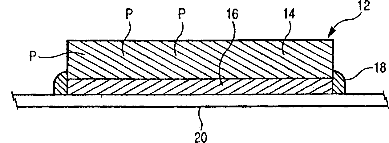
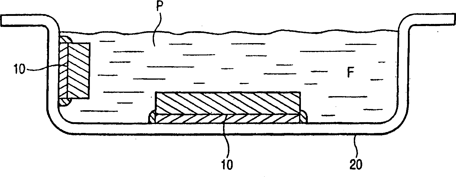
[0024] In general, some embodiments of the present invention provide filtration systems utilizing two-part filters. The two-part filter includes a fibrous region substantially adjacent to a magnetic region, which is typically disposed near an interior surface of the liquid handling system, and the fibrous region extends into the liquid to be filtered. The system may include a housing forming a lip around the perimeter of the two-part filter. In other embodiments, the magnetic material may be part or all of the fiber region itself, the discrete parts being optional.

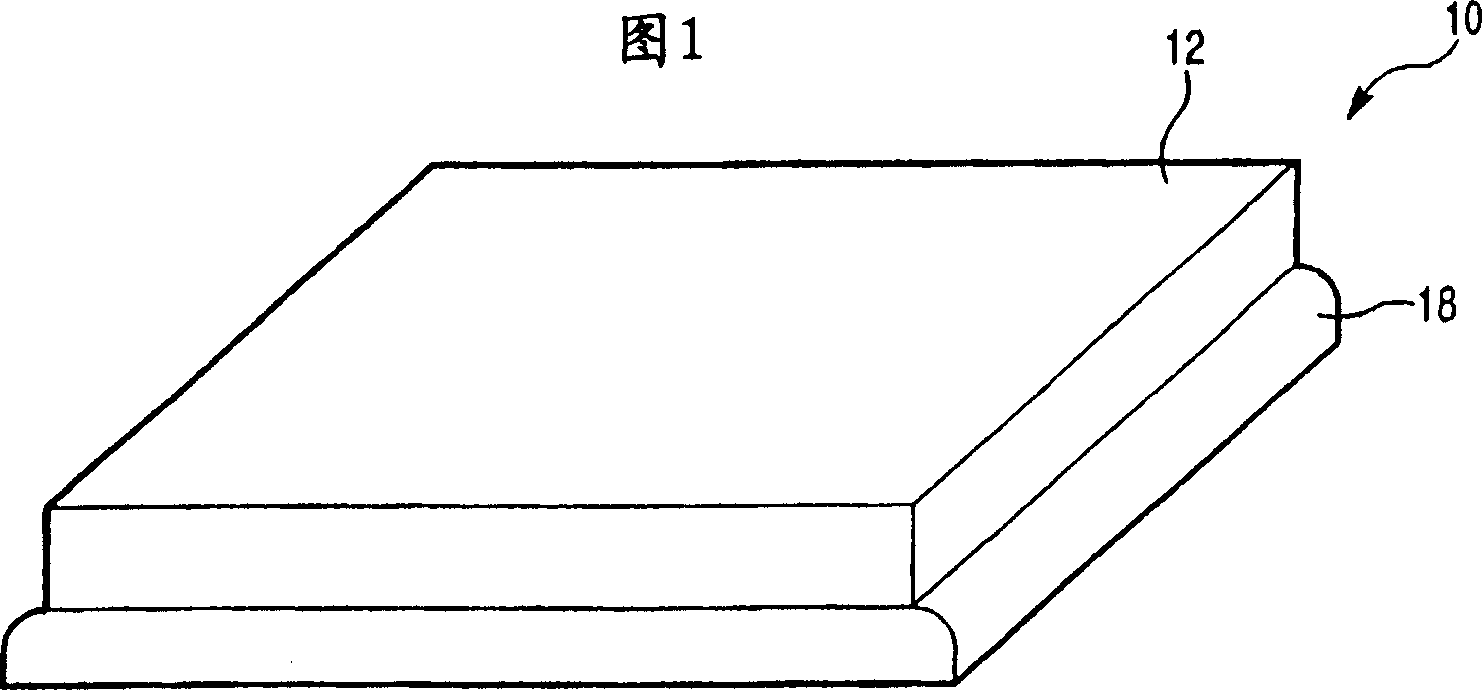
[0025] Referring now to the drawings, and in particular FIGS. 1 and 2 , an embodiment of a filtration system includes a magnetic filtration system for filtering metal particles from a liquid in a liquid container of a mechanical system, and includes a first magnetic layer and a magnetic layer adjacent to and overlying the magnetic layer. the second fiber layer.

[0026] More specifically, filtration system 10 in...


PUM


Abstract

A magnetic filter system for filtering metallic particles from a fluid is mounted inside a fluid vessel in a mechanical system, and includes a first magnetic layer and a second fibrous layer adjacent to and overlaying the magnetic layer.

Description

[0001] priority [0002] This application claims priority to US Patent Application Serial No. 10 / 096,902, filed March 14, 2002, and entitled "Fibrous Filter Assembly And Method." technical field [0003] The field to which this invention relates generally is that of filtering fluids in sumps or other fluid handling systems. More particularly, the present invention relates to filters that can be used in wet mechanical systems, for example, which may not necessarily have any pressurized fluid system for circulating the fluid. Furthermore, the field of the invention is the use of magnetic fields in these systems in order to magnetically attract and retain magnetic particles from the liquid being filtered. Background technique [0004] There are many applications that require filtration of liquids in mechanical systems. For example, internal combustion engines, vehicle transmissions, and gearboxes often contain sumps with motor oil or another suitable lubricant. [0005] Some...

Claims


Application Information

Patent Timeline
Patent Type & Authority Applications(China)
IPC IPC(8): B01D39/14B01D35/06B03C1/00B03C1/28F01M11/00F01M11/03F16H57/04
CPCB01D35/06B03C1/286F01M2011/0079B03C2201/18F01M11/03F16H57/0404F01M2001/1042F16H57/0482
Inventor 约翰·G·埃利夫瑟拉基斯约翰·E·亚当斯阿贝·卡利尔
Owner SPX CORP
Why Eureka
Try Eureka