Combustion chamber

A combustion chamber and combustion cavity technology, which is applied in the field of combustion chambers, can solve problems such as installation costs, operation downtime costs, high maintenance and repair costs, and labor-intensive assembly work, and achieve small cooling medium pressure loss, low manufacturing costs, and reduced Effect of small cooling medium pressure loss

Inactive Publication Date: 2004-08-11
SIEMENS AG
View PDF0 Cites 15 Cited by
  • Summary
  • Abstract
  • Description
  • Claims
  • Application Information

AI Technical Summary

Problems solved by technology

Therefore, the assembly work is also very labor-intensive and time-consuming.
Since the gas turbine is out of service for a relatively long period of time, in addition to the installation cost of the gas turbine, there are incidental downtime costs, which lead to a relatively higher overall maintenance and repair cost for the gas turbine

Method used


Image

  • Combustion chamber
  • Combustion chamber
  • Combustion chamber

Examples


Embodiment Construction

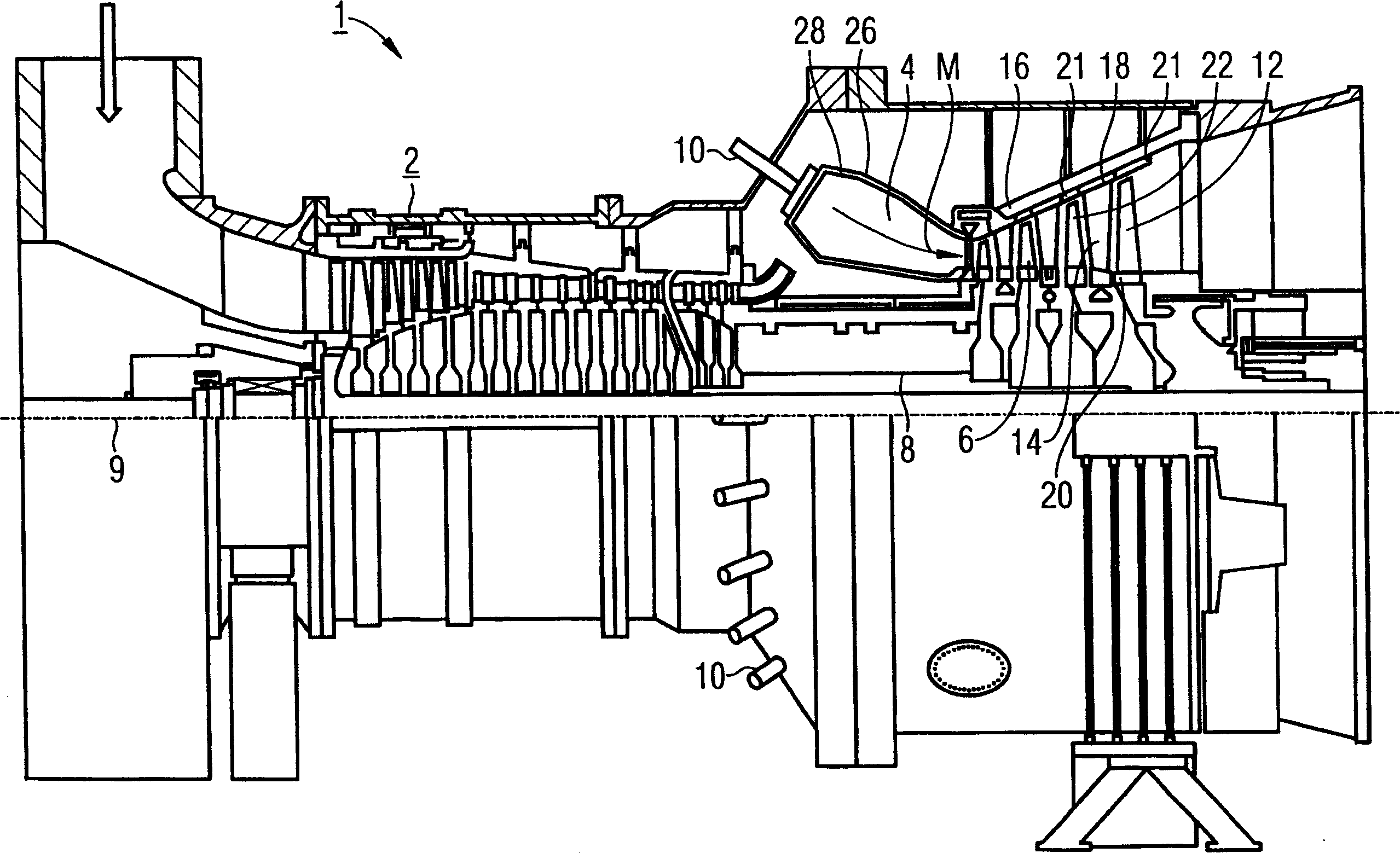
[0029] figure 1 The gas turbine 1 shown has a compressor 2 for providing combustion air, a combustion chamber 4 and a turbine 6 for driving the compressor 2 and a generator or working machine not shown in the figure . Here, the turbine 6 and the compressor 2 are mounted on a common turbine shaft 8 , also referred to as the turbine rotor, to which the generator or power machine is connected. And the turbine shaft is mounted rotatably about its axis 9 . The combustion chamber 4, designed in the form of an annular combustion chamber, is equipped with burners 10 for burning a fuel in liquid or gaseous form.

[0030] The turbine 6 has rotatable rotor blades 12 connected to the turbine shaft 8 . The rotor blades 12 are mounted in a circle on the turbine shaft 8 and thus form rotor blade groups. In addition, the turbomachine 6 also includes stationary guide vanes 14 which are likewise fastened in the inner housing 16 of the turbomachine 6 in the shape of a circle while forming a ...


PUM


Abstract

A combustion chamber (4) of a gas turbine (1), the combustion space (24) of which is bounded by an annular combustion chamber inner wall (28) and a combustion chamber outer wall,(26), in which in order to generate a working medium (M) a supplied fuel is brought into reaction with supplied combustion air, and the combustion chamber wall (25) of which is provided on the inside with a lining formed from a plurality of heat shield elements (38), with the or each heat shield element (38) together with the combustion chamber wall (25) forming an inner space (40) to which a cooling medium (K) can be applied, is to be designed so as to provide a high level of system efficiency at the same time as having a comparatively simple structure and it should also be possible to disassemble the combustion chamber inner wall (28) in a time-saving manner. For this purpose according to the invention there is disposed in each case in the respective inner space (40) a cooling medium distributor (42) via which a cooling medium supply line (44) is connected to a plurality of cooling medium exit openings (46) and the combustion chamber inner wall (28) is formed from a plurality of wall elements (30) abutting each other at a horizontal parting joint (31), whereby the abutting wall elements (30) of the combustion chamber inner wall (28) are connected to one another at their horizontal parting joint (31) by means of a plurality of screw connections (32) oriented at an angle to the inner wall surface.

Description

technical field [0001] The invention relates to a combustion chamber for a gas turbine, the combustion chamber of which is delimited by an annular outer wall and an annular inner wall arranged in the outer wall. The inside of the combustion chamber wall is lined with heat shielding elements, wherein the heat shielding elements form an interior space into which a cooling medium can enter. Furthermore, the invention relates to a gas turbine having a combustion chamber of this type. Background technique [0002] Combustion chambers are an integral part of gas turbines, which are used in many fields as drives for generators and working machines. In this, the energy contained in a fuel is used to generate a rotational movement of a turbine shaft. For this purpose, fuel is ignited by burners and burned in combustion chambers connected behind them, while compressed air is introduced by an air compressor. A high-temperature working medium under high pressure is produced by the co...

Claims


Application Information

Patent Timeline
Patent Type & Authority Applications(China)
IPC IPC(8): F23R3/42F02C7/16F02C7/18F23R3/00F23R3/50F23R3/60
CPCF23R2900/03044F23R3/007F23R3/60F23R3/50F23R3/005
Inventor 保罗-海因茨·杰普尔威廉·舒尔滕
Owner SIEMENS AG
Why Eureka
Try Eureka