Lapping apparatus and lapping method

A device, a technology for lapping films, applied in grinding/polishing equipment, lapping devices, lapping machine tools, etc., to solve problems such as hindering smooth operation of valves

Inactive Publication Date: 2004-08-18
NISSAN MOTOR CO LTD
View PDF1 Cites 9 Cited by
  • Summary
  • Abstract
  • Description
  • Claims
  • Application Information

AI Technical Summary

Problems solved by technology

Since these action areas are an important part of, for example, starting the engine to open and close the valve, greater surface roughness may hinder the smooth operation of the valve

Method used


Image

  • Lapping apparatus and lapping method
  • Lapping apparatus and lapping method
  • Lapping apparatus and lapping method

Examples


no. 1 example

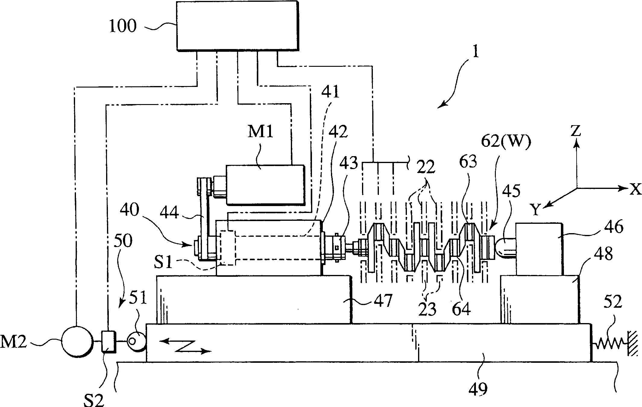
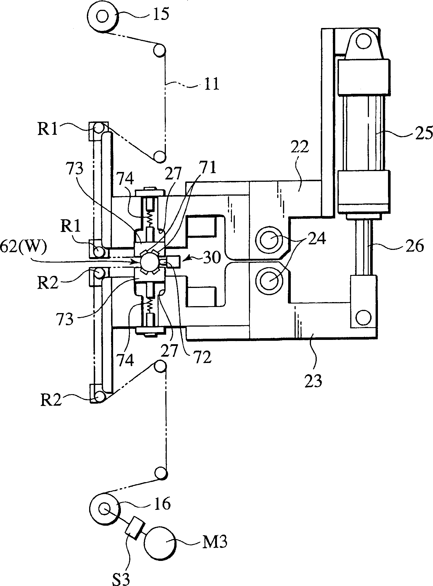
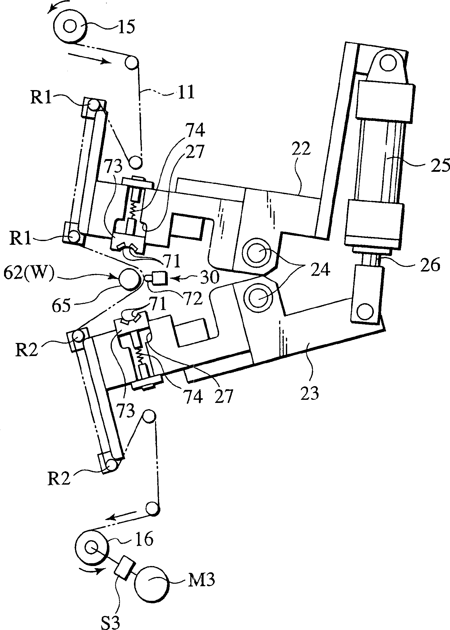
[0050] figure 1 A grinding apparatus 1 according to a first embodiment of the present invention is shown. figure 2 The closed state of the upper and lower arms 22, 23 provided in the grinding apparatus 1 in an openable and closable manner is shown. image 3 The open state of the upper and lower arms 22, 23 is shown. Figure 4A and 4B The essential parts of the grinding apparatus 1 are shown, wherein Figure 4A A state is shown in which the second bottom plate 72 constituting the soft bottom plate is driven to the operating position in which the second bottom plate 72 is pushed toward the mouth base 67 of the lubricant hole 66, and Figure 4B A state is shown in which the soft soleplate is driven to an inoperative position in which the soft soleplate is separated from the mouth base 67 of the lubricant hole 66 . 5A to 5C as well as 6A to 6C The range in which the soft soleplate 72 is driven between the non-operating position and the operating position is shown. Figure...

no. 2 example

[0092] Figure 10 The closed state of the upper and lower arms 22, 23 provided in the grinding apparatus 2 according to the second embodiment of the present invention in an openable and closable manner is shown. in addition, Figure 11A and Figure 11B The bottom plate 80 and the bottom plate shell 83 used in the second embodiment are shown. It should be noted that the same elements in the second embodiment as those in the first embodiment are denoted by the same reference numerals as in the first embodiment, and descriptions thereof will be omitted.

[0093] like Figure 10 As shown, the grinding apparatus 2 according to the second embodiment is suitable for grinding a crankshaft 62 as a workpiece W having the same opening portion 66 (such as a lubricant) formed with an opening as in the first embodiment. The pre-machined surface 65 of the hole), and the polishing apparatus 2 includes the polishing film 11 and the base plate 80 for pressing the abrasive-grained surface of...

no. 3 example

[0111] Hereinafter, a third embodiment of the present invention will be described with reference to the accompanying drawings. The same elements in the third embodiment as those in the first embodiment are denoted by the same reference numerals as in the first embodiment, and descriptions thereof will be omitted.

[0112] Figure 12 A grinding apparatus 3 according to a third embodiment of the present invention is shown. Figure 13 The closed state of the upper and lower arms 22, 23 provided in the grinding apparatus 3 in an openable and closable manner is shown. figure 1 4 shows the open state of the upper and lower arms 22, 23. Figure 15 The essential parts of the grinding device 3 are shown. also, Figure 16Camshaft position with vibration is shown. Figure 17 The structure corresponding to the chassis pressing unit 330 (as opposed to the chassis driving unit) is shown. Figure 18 Changes in the bottom plate pressing force P are shown. and, Figure 19A An exemplar...


PUM


Abstract

A lapping apparatus lapping a work having a pre-machined surface comprises a lapping film which includes a thin substrate having a surface provided with abrasive grains, a shoe disposed at a back surface side of the lapping film, a shoe driving unit which drives the shoe toward the work in order to press the abrasive-grained surface of the lapping film to the pre-machined surface of the work, a rotational driving unit which drives the work rotationally, a detecting unit which detects the position of the rotating work in the rotating direction, and a controlling unit which controls the pressing force of the shoe driving unit so as to drive the shoe correspondingly to the position of the work in the rotating direction during machining.

Description

technical field [0001] The present invention relates to a grinding apparatus and a grinding method for film-grinding (hereinafter abbreviated as "grinding") processing of a pre-machined surface of a workpiece by means of a grinding film with abrasive grains (hereinafter occasionally abbreviated as "film"). Background technique [0002] In recent years, in the case of polishing a workpiece having an outer circumferential surface of an arc-shaped cross section, such as a pin portion and a shaft portion of a crankshaft or a cam lobe portion and a journal portion of a camshaft, one surface equipped with a grinding wheel is used. The abrasive film of the particles is polished. [0003] The lapping is to process the workpiece with the abrasive grained surface of the film by covering the pre-machined surface of the workpiece with a polishing film, and by rotating the workpiece while the base plate presses the film against the workpiece from the rear surface thereof. In addition to...

Claims


Application Information

Patent Timeline
Patent Type & Authority Applications(China)
IPC IPC(8): B24B37/02B24B5/42B24B19/12B24B21/00B24B49/16
CPCB24B21/00B24B5/42B24B19/12B24B49/16B24B21/16B24B37/00
Inventor 长谷川清饭泉雅彦小又正博荻野崇近藤智浩武田和夫渡边孝文千田义之松下靖志
Owner NISSAN MOTOR CO LTD
Why Eureka
Try Eureka