Surface finishing apparatus and related method

A surface finishing and workpiece technology, applied in the field of surface finishing devices, can solve problems such as troublesome implementation and expensive roller polishing tools

Inactive Publication Date: 2004-08-18
NISSAN MOTOR CO LTD
View PDF2 Cites 12 Cited by
  • Summary
  • Abstract
  • Description
  • Claims
  • Application Information

AI Technical Summary

Problems solved by technology

[0008] In addition, the roll polishing operation in the prior art has the problem that it is cumbersome to implement and the roll polishing tool itself is expensive

Method used


Image

  • Surface finishing apparatus and related method
  • Surface finishing apparatus and related method
  • Surface finishing apparatus and related method

Examples


no. 1 example

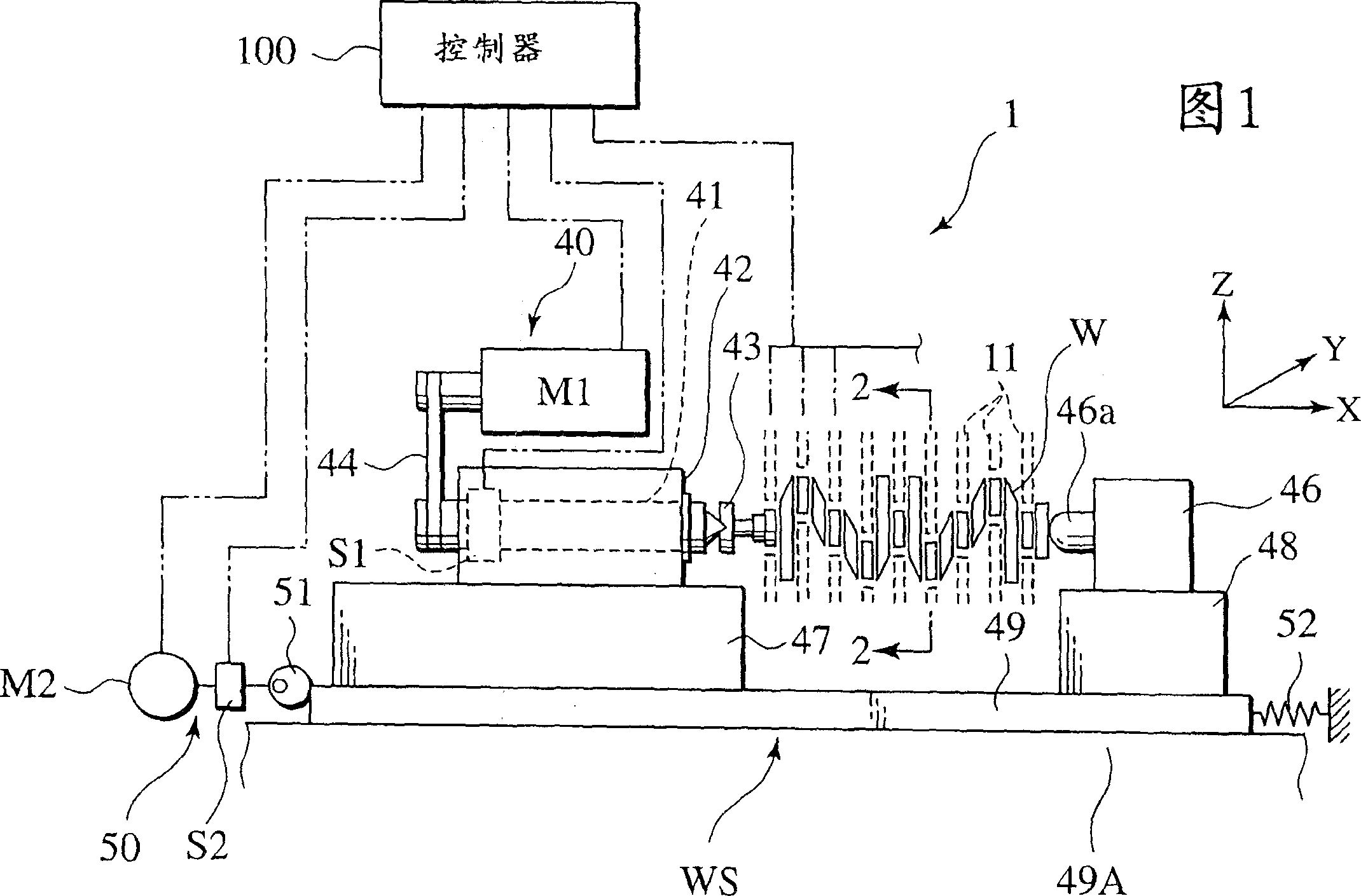
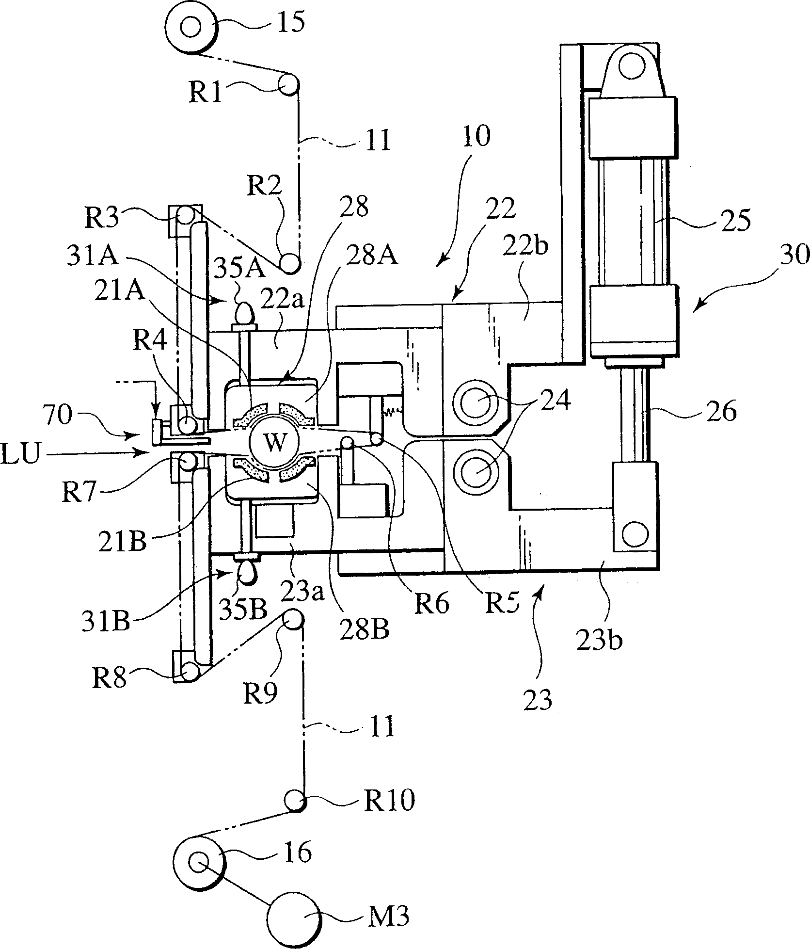
[0059] Referring now to FIGS. 1 and 2, there is shown a first embodiment of a surface finishing apparatus according to the present invention as a grinding apparatus 1. Referring to FIG. Figure 1 is a schematic front view of the grinding device, figure 2 is a schematic diagram corresponding to the cross-section of line 2-2 in Fig. 1 .

[0060] As shown in FIGS. 1 and 2, the grinding apparatus 1 in the presently described embodiment is used to finely grind a workpiece W in the form of a crankshaft in a surface finishing operation following a surface roughing operation such as : A cutting operation, a heat treatment operation, and a grinding operation are performed with one processing tool. That is, the grinding device 1 is used to grind a target shaped periphery of a workpiece W, such as a connecting portion or a pin portion of a crankshaft, to a desired surface quality having a concave surface profile. The shown grinding device 1 includes: a workpiece supporting mechanism WS...

no. 2 example

[0104] The following will refer to Figures 8 to 14 and Figure 15A with 15B A surface finishing apparatus 1A of a second embodiment of the present invention is described. FIG. 8 is a schematic diagram illustrating a surface finishing apparatus 1A of a second embodiment of the present invention. Figure 9 is the positional relationship corresponding to figure 2 is a schematic diagram showing a pressure applying mechanism 10A forming part of the surface finishing device 1A, the upper and lower pressing arms of the pressure applying mechanism 10A can be manipulated to assume an open state and a closed state, and in the Figure 9 , the upper and lower pressing arms are closed. Figure 10 The pressure applying mechanism 10A is schematically shown with the upper and lower pressing arms in the opened state. Figure 11 is a partially enlarged cross-sectional view showing the presser mechanism of the surface finishing apparatus 1A of the presently described embodiment, which consti...

no. 3 example

[0166] Figure 22 Schematically represents a surface finishing device according to a third embodiment of the present invention, Figure 23 yes Figure 22 A cross-sectional cutaway view of the surface finishing device shown, with the pin portion of the workpiece shown in slightly exaggerated form.

[0167] The surface finishing device of the third embodiment differs from the first embodiment in that the surface finishing device of the presently described embodiment takes the form of a roller polishing device which passes a surface in the form of a polishing roller under pressure. The finishing tool is brought into contact with the workpiece W by a pressure exhibiting a given distribution pattern according to the axial direction of the workpiece, which has been initially ground in surface finishing to have such Figure 5 A workpiece with a concave profile cross-section as shown is roll polished. Therefore, the same reference numerals are used for the same components as those ...


PUM


Abstract

An apparatus and method for surface finishing a workpiece is disclosed as including a workpiece supporting mechanism supporting a workpiece having a target shaped periphery with a given width to be surface finished and a tool holder holding a surface finish tool in abutting contact with the target shaped periphery of the workpiece. A pressure applying mechanism is operative to apply a pressure force to the surface finish tool through the tool holder to cause the surface finish tool to be held in pressured contact with the target shaped periphery, with the pressure force exhibiting a given distribution pattern depending upon an axial direction of the workpiece. A drive mechanism rotates the workpiece to allow the surface finish tool to surface finish the target shaped periphery into a given geometrical profile, variably contoured along an axis of the workpiece depending on the given pressure distribution pattern.

Description

technical field [0001] The present invention relates to a surface finishing device and an associated method, and more particularly, to such a surface finishing device and an associated method, which are used to process the surface of a workpiece along the axial direction of the workpiece Finishing is a desired geometric profile. Background of the invention [0002] In the past, various attempts have been made to grind the target shaped periphery of an automotive engine crankshaft, such as a journal or pin portion, and then roll polish the resulting surface to a desired surface roughness. [0003] The aforementioned lapping operation in surface finishing is achieved by allowing a lapping film to cover the target shaped periphery of the workpiece and placing a plurality of shoes on the back side of the lapping film, thereby maintaining pressure between the lapping film and the workpiece. In the event of contact, the workpiece is rotated to allow the abrasive surface of the ab...

Claims


Application Information

Patent Timeline
Patent Type & Authority Applications(China)
IPC IPC(8): B24B5/42B24B19/12B24B21/00B24B49/16
CPCB24B21/00B24B5/42B24B19/12B24B49/16
Inventor 近藤智浩饭泉雅彦小又正博长谷川清荻野崇渡边孝文千田义之松下靖志武田和夫
Owner NISSAN MOTOR CO LTD
Why Eureka
Try Eureka