Apparatus for driving liquid crystal display device

A technology of liquid crystal display device and driving device, which is applied in static indicators, cathode ray tube indicators, optics, etc., and can solve difficult problems

Inactive Publication Date: 2004-09-08
HYDIS TECH CO LTD
View PDF0 Cites 8 Cited by
  • Summary
  • Abstract
  • Description
  • Claims
  • Application Information

AI Technical Summary

Problems solved by technology

At this time, very difficult technology is required to design 36 to 48 image signals and more than 10 control signals

Method used


Image

  • Apparatus for driving liquid crystal display device
  • Apparatus for driving liquid crystal display device
  • Apparatus for driving liquid crystal display device

Examples


Embodiment Construction

[0013] An embodiment of the present invention will be described in detail below with reference to the accompanying drawings. In the drawings, the same reference numerals are used to denote the same or similar structural elements or signals.

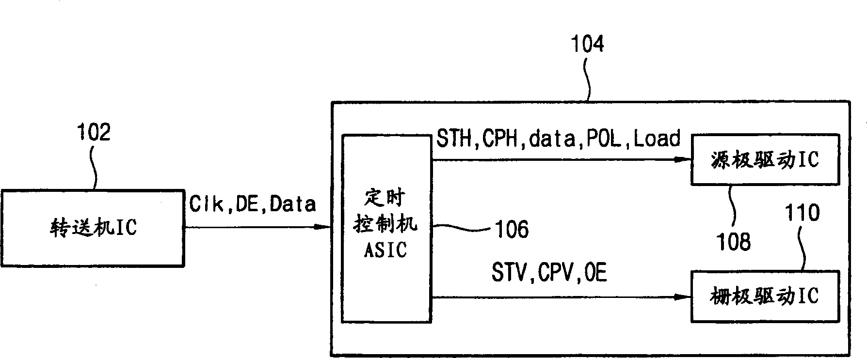
[0014] Schematic diagram of the currently used TFT LCD driver and figure 1 same as shown in the illustration. The source driver IC latches each data of RGB sequentially input by the controller according to the dot clock, and the timing system of the dot sequential method is changed to the line sequential method. The data stored in the first latch is transferred to the second latch in coordination with the transition start signal at each horizontal line period. The data stored in the second latch is converted into an analog voltage in the analog / digital converter, and then applied to the data line through the current buffer. In order to perform such data conversion, the following signals are required as basic control signals. exist fi...


PUM


Abstract

A device for driving an LCD includes a timing control unit, a gate driving unit having a shift register and an output circuit, and a control signal transmission line for transmitting a data carry signal for enabling the shift register and a signal for controlling an data output by the output circuit using a single signal line. The data carry signal uses a rising edge trigger system, and the output control signal uses a level trigger system. In order to prevent an overlapping of the data carry signal and the output control signal, the output control signal is outputted after one clock from a time point where the data carry signal is latched using the shift register.

Description

technical field [0001] The present invention relates to a liquid crystal display device, and particularly relates to a driving device for a liquid crystal display device in which the method of transmitting a control signal between a timing control IC and a gate driver IC is newly specified. Background technique [0002] In order to drive the existing liquid crystal display (Liquid Crystal Display: LCD), a driver IC (Integrated Circuit), a timing controller ASIC and an analog circuit are required in the LCD panel. The main function of the timing control machine ASIC is to receive RGB signals through the host interface (Host Interface), distribute data in each source driver IC, and control the gate driver IC. [0003] For the purpose of controlling the source driver IC, the main control signals generated in the timing controller ASIC are the carry signal (STH) that notifies the source driver IC of the start of data, the signal that notifies the polarity of the output voltage (...

Claims


Application Information

Patent Timeline
Patent Type & Authority Applications(China)
IPC IPC(8): G02F1/133G09G3/20G09G3/36G09G5/18
CPCG09G5/18G09G3/3685G09G3/36
Inventor 郑韵衡
Owner HYDIS TECH CO LTD
Why Eureka
Try Eureka