Active shock-reducing circuit for synchronous rectifying device

A technology of active damping and synchronous rectifier, which is applied in the direction of output power conversion device, electrical components, regulating electrical variables, etc., which can solve the problems of circuit complexity and component cost increase, high voltage spikes of synchronous rectifiers, and poor reverse recovery characteristics.

Active Publication Date: 2004-09-08
DELTA ELECTRONICS INC
View PDF0 Cites 12 Cited by
  • Summary
  • Abstract
  • Description
  • Claims
  • Application Information

AI Technical Summary

Problems solved by technology

However, since the driving signal of the active switching switch Sa is obtained from the primary side through an additional isolated driving circuit, the circuit complexity and component cost will be greatly increased
[0006] Although synchronous rectifiers have been widely used in low-voltage and high-current DC / DC converters, however, due to the poor reverse recovery characteristics of the body diodes of synchronous rectifiers, there may be high voltage spikes in synchronous rectifiers

Method used


Image

  • Active shock-reducing circuit for synchronous rectifying device
  • Active shock-reducing circuit for synchronous rectifying device
  • Active shock-reducing circuit for synchronous rectifying device

Examples


Embodiment Construction

[0051] Although the present invention can be embodied in many different forms, some preferred embodiments will be described in detail below. It is important to note that the disclosure of the present invention is intended as an illustration of the principles of the invention and is not intended to limit the invention's broader characteristics to the particular embodiments described.

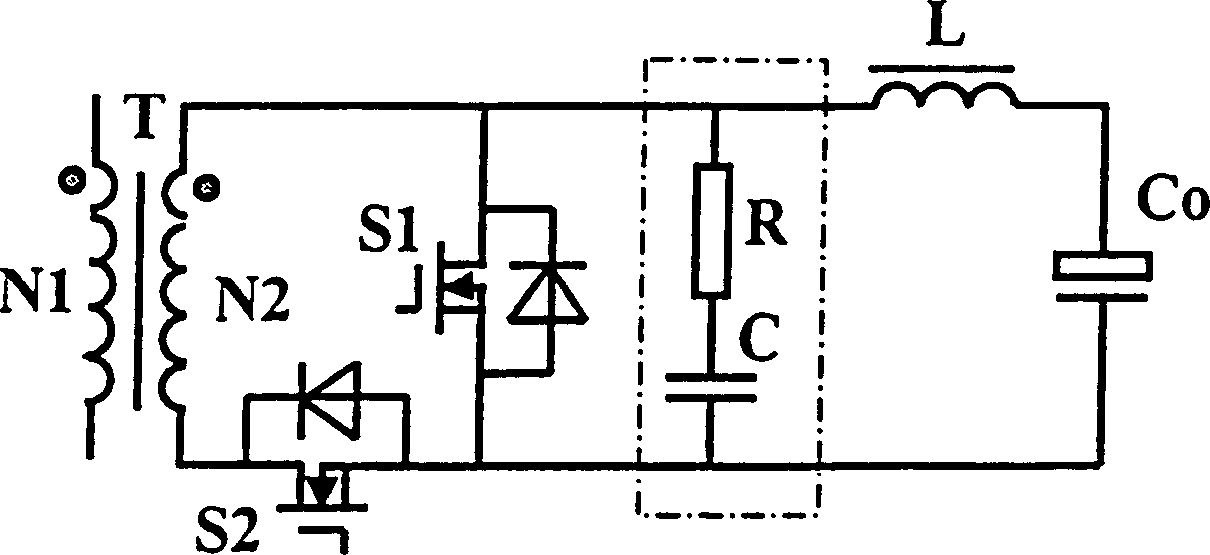
[0052] Please refer to Figure 4 , which is a schematic diagram of an active damping circuit applied to a half-wave synchronous rectifier circuit according to the first preferred embodiment of the present invention. Among them, the half-wave synchronous rectifier has a transformer T, which has a primary side coil N1 and a secondary side coil N2. This synchronous rectifier includes a synchronous MOS transistor S1 with a flywheel function and a forward synchronous MOS transistor S2, both of which are coupled to the transformer T, and the positive terminal of the secondary coil N2 is connected to t...


PUM


Abstract

The present invention is one kind of active shock-reducing circuit coupled to one synchronous rectifier, which has the first synchronous switching device and the second synchronous switching device and is coupled to one transformer of one power converter. The active shock-reducing circuit includes: one serial combination of one switch and one first shock-reducing capacitor and coupled to the first synchronous switching device, and one grid driver to make the switch on for one certain time during the non-conducting period of the first synchronous switching device. The grid driver includes one auxiliary coil, one capacitor connected to one end of the capacitor and one resistor, to which the serial branch of auxiliary coil and the capacitor is connected. The serial branch is also connected parallelly to the switch.

Description

(1) Technical field [0001] The present invention relates to a power supply device, especially an active damping circuit for a synchronous rectifier to reduce voltage spikes and high-frequency harmonics caused when the synchronous rectifier is turned off. (2) Background technology [0002] Synchronous rectification is widely used in low voltage and high current direct current / direct current (DC / DC) converters. As known in the art, in a conventional half-wave synchronous rectifier, a synchronous metal oxide semiconductor transistor (MOSFET) is selectively turned on or off to synchronize with the secondary side voltage of the isolation power transformer. Using this method, the secondary side voltage of the power transformer is rectified and delivered to the output. However, there may be high voltage spikes and high frequency harmonics between the drain and source of this freewheel synchronous MOSFET. This type of voltage spike is caused by the poor reverse recovery characteri...

Claims


Application Information

Patent Timeline
Patent Type & Authority Applications(China)
IPC IPC(8): H02M1/34H02M3/335
CPCH02M1/34Y02B70/1475H02M2001/342H02M3/33592Y02B70/1491H02M1/342Y02B70/10
Inventor 熊雅红柯忠伟章进法
Owner DELTA ELECTRONICS INC
Why Eureka
Try Eureka