Piston crankshaftless engine

An engine, crankless technology, applied in the direction of machine/engine, mechanical equipment, etc., can solve the problems of complex movement mode, complex structure of moving parts, etc., to achieve the effect of simple replacement of parts and simplification of constituent elements

Inactive Publication Date: 2013-03-20
程远
View PDF4 Cites 0 Cited by
  • Summary
  • Abstract
  • Description
  • Claims
  • Application Information

AI Technical Summary

Problems solved by technology

[0004] Purpose of the invention The present invention overcomes the defects of complex structure and complex motion mode of moving parts in the above-mentioned documents, and aims to provide a simple structure of the reciprocating and rotating power conversion mechanism of the engine

Method used


Image

  • Piston crankshaftless engine
  • Piston crankshaftless engine
  • Piston crankshaftless engine

Examples


Embodiment Construction

[0043] Below in conjunction with accompanying drawing and specific embodiment, technical scheme of the present invention is described further:

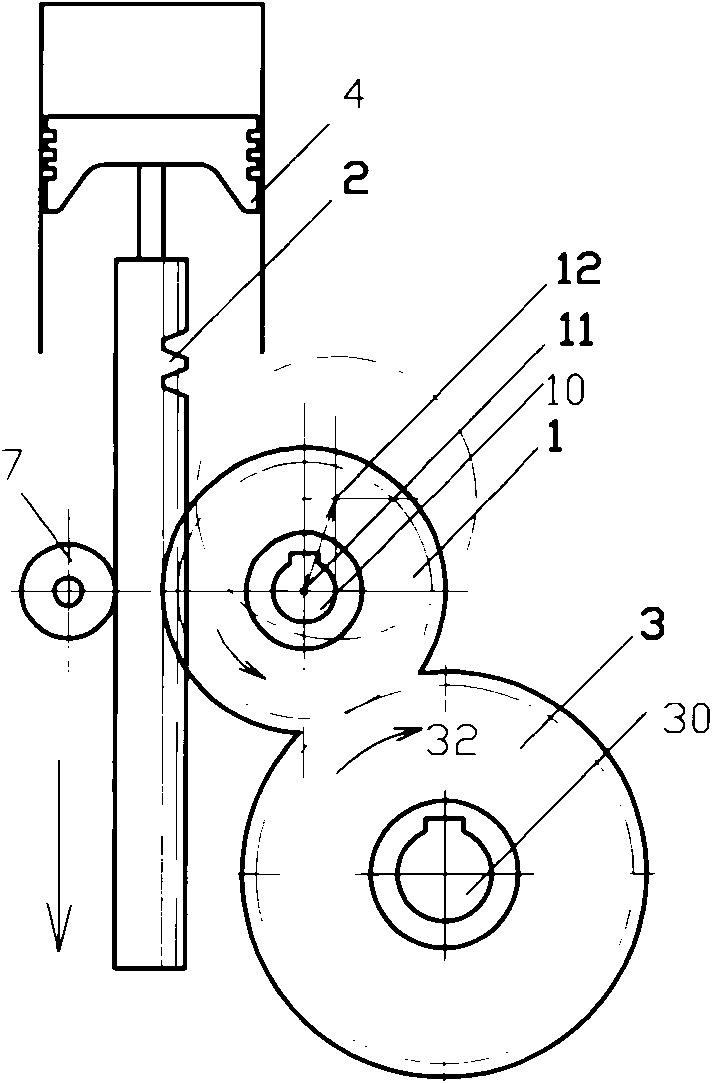
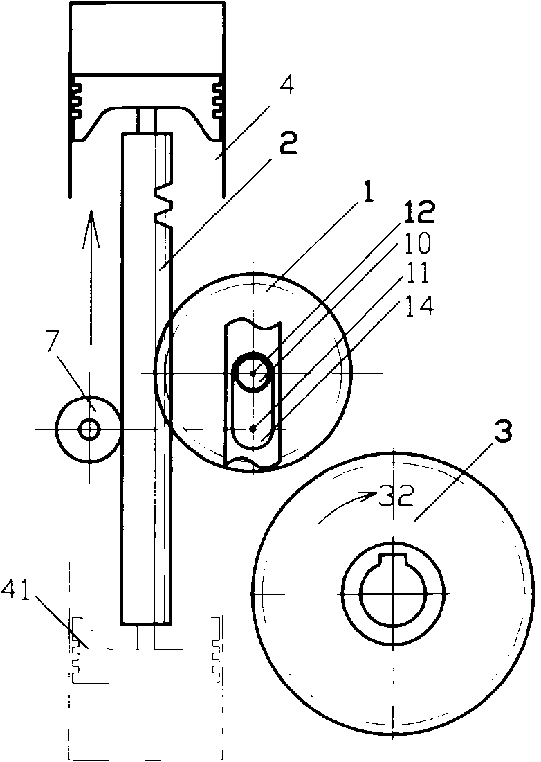
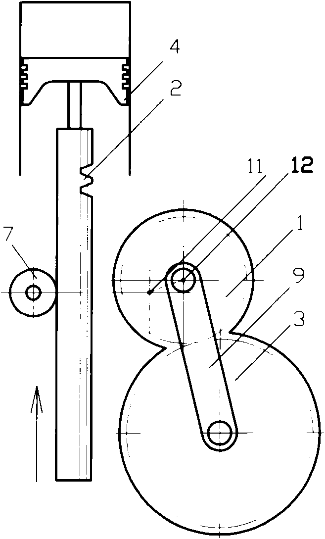
[0044] 1. If figure 1 Is a typical embodiment, the core component - the mobile gear 1 can move between the "engagement" position 11 and the "non-engagement" position 12 . When the rigid member formed by the solid connection of piston 4 and rack 2 runs from the top dead center to the bottom dead center, the moving gear 1 moves to the "engagement" position 11, that is, the moving gear 1 is directly meshed with the rack 2, and at the same time it is also in contact with the drive The gear 3 is also directly meshed, so that the power transmission link among the piston 4, the rack 2, the moving gear 1, the driving gear 3, and the straight output spindle 30 is communicated. If the piston 4 is in the explosive stroke, its explosive power can follow the power The transmission chain is transmitted tangentially by the rack 2 to the moving gear...


PUM


Abstract

The invention discloses a kind of piston engine without crank, a power converting mechanism made up of mobile gear, gear rack connected to the piston and the driving gear fixed on the straight output main shaft replaces traditional crank link mechanism, and it overcomes the deficiency of current crank-less engine; the mobile gear can move between the connection position and the non-connection position, thus the dynamic force device between the gear rack and the driving gear can be in on / off state; in the exposure distance of the piston, it can transmit force to the main shaft through the force transmitting chain; the back movement of piston doesn't affect the movement of the output main shaft; along with the joining movement of mobile gear, by mating with the other assistant system, the reciprocate straight movement can be changed into the power output with continuous single direction rotation of main shaft. The converter can be used in gasline, diesel, gas inner combustion machine.

Description

technical field [0001] The invention relates to piston engines, including gasoline, diesel, gas and other internal combustion engines, as well as piston steam engines, etc., especially to piston engines without a crankshaft. Background technique [0002] In the current crankless piston engine field, the reciprocating and rotating power conversion mechanisms that replace the crankshaft-connecting rod mechanism are mostly mechanisms composed of parts such as racks and gears. After a comprehensive search, the closest comparative document to this technical solution is: French Patent FR2799231A published on April 6, 2001 - "Converting machinery dedicated to converting reciprocating linear motion into continuous circular motion for internal combustion engines and compressors": In this technical solution, there are transmission parts ETC (including racks) fixedly connected with piston P and reciprocating, intermediate gear PM and its driving shaft AM (that is, driving gear and shaf...

Claims


Application Information

Patent Timeline
Patent Type & Authority Patents(China)
IPC IPC(8): F02B75/32
Inventor 程远
Owner 程远
Why Eureka
Try Eureka