Optical scanning outside diameter measuring system without scanning objective lens and its measuring method

An optical scanning and measurement system technology, applied in the direction of measuring devices, optical devices, instruments, etc., can solve the problems of scanning objective lens design, manufacturing and assembly difficulties, errors are difficult to fully compensate, and the dynamic measurement range is limited. Reduced location requirements, improved reliability, and convenient commissioning and maintenance

Inactive Publication Date: 2004-09-15
SOUTH CHINA UNIV OF TECH
View PDF0 Cites 4 Cited by
  • Summary
  • Abstract
  • Description
  • Claims
  • Application Information

AI Technical Summary

Problems solved by technology

[0003] 1. The accuracy of the scanning system mainly depends on the processing and installation accuracy of the high-precision scanning objective lens. In terms of principle, it is difficult to fully compensate for the errors caused by the design and manufacture of the scanning objective lens, and the dynamic measurement range under the premise of high precision is limited.
[0004] 2. The design, manufacture and assembly of the above-mentioned scanning objective lens are relatively difficult, so the production efficiency is low and the manufacturing cost is high, which limits the popularization and use of the equipment
[0005] 3. When the system is in use, since temperature changes affect the accuracy of the scanning objective lens, the system has high environmental requirements in actual use. In general production environments, the system reliability is not high
[0006] 4. The measurement range is limited by the size of the scanning objective lens, and it is difficult to expand the measurement range

Method used


Image

  • Optical scanning outside diameter measuring system without scanning objective lens and its measuring method
  • Optical scanning outside diameter measuring system without scanning objective lens and its measuring method
  • Optical scanning outside diameter measuring system without scanning objective lens and its measuring method

Examples


Embodiment Construction

[0026] The present invention will be described in further detail below in conjunction with the accompanying drawings and embodiments.

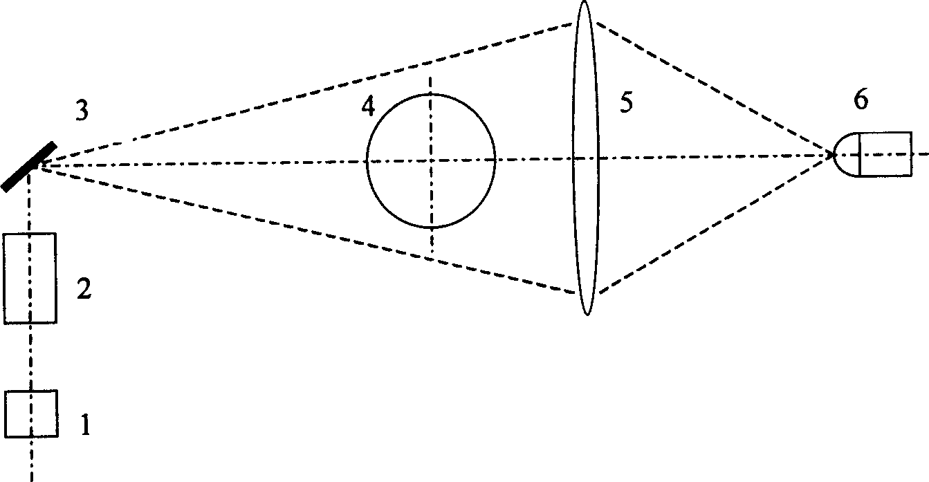
[0027] Such as figure 1 As shown, each unit is composed of a light source 1, a collimator mirror 2, a scanning mirror 3, a receiving objective lens 5, and a photoelectric receiver 6 connected to each other in sequence, and the photoelectric receiver 6 is also connected to a computer through a signal line. The light source (laser light source or LED light source) 1 is collimated by the collimator mirror 2 and projected on the scanning mirror 3 to form a scanning beam. The scanning beam scans the object 4 to form a scanning shadow, which is received by the subsequent photoelectric receiving lens 5 through the receiving objective lens 5. Receiver 6 receives, and processing circuit sends computer after signal processing, constitutes the basic unit of the present invention. The scanning mirror 3 has one or more reflective surfaces, the receiving o...


PUM


Abstract

The invention is a kind of optical scanning external diameter measuring system which hasn't the scanning object lens and the measuring method. The system is made up of two or more optical scanning units without scanning object lens, each unit is assembled with any angle, each unit is made up by connecting light source, collimating mirror, scanning rotary mirror, the receiving object lens, photoelectric receiver. The photoelectric receiver connects with computer through wires. The method uses any two units as a group, the distance between the scanning mirror and the reflection centre point is l0, the offset centre angle to light of the measured object are 2theta 1 and 2 theta 2, the line between the object gravity center and the scanning mirror reflection centre point are alpha 1, alpha 2, the diameter is d: d= dkl0 according to following method, k= 1/(cos alpha 1/ sin theta 1 + cos alpha 2/ sin theta 2). The invention has no object lens, the producing is easy, it realiezes the computer digit compensate for system difference, the stability is good, it has high reliability, the assemble and maintaining is easy, the cost is low.

Description

technical field [0001] The invention relates to the technical field of geometric quantity measuring equipment, in particular to an optical scanning outer diameter measuring system without a scanning objective lens and a measuring method thereof. Background technique [0002] The existing optical scanning outer diameter measurement system is composed of light source, collimating mirror, reflective rotating mirror, scanning objective lens, receiving objective lens and photoelectric device. The deflection light on the mirror becomes the scanning measurement light after scanning the objective lens. The scanning light is blocked by the measured object to form a shadow. After receiving and measuring the width of the shadow, the size of the object can be obtained. The prior art has the following problems in design, manufacture and practicality: [0003] 1. The accuracy of the scanning system mainly depends on the processing and installation accuracy of th...

Claims


Application Information

Patent Timeline
Patent Type & Authority Applications(China)
IPC IPC(8): G01B11/08G01D5/12
Inventor 马国欣
Owner SOUTH CHINA UNIV OF TECH
Why Eureka
Try Eureka