Electric imaging system using organic laser matrix radiation area light valve

An electrical imaging and laser technology, applied to the structure/shape of lasers, laser components, and optical resonators, to achieve the effect of suppressing the appearance of laser spots and improving image uniformity

Inactive Publication Date: 2004-09-29
EASTMAN KODAK CO
View PDF9 Cites 21 Cited by
  • Summary
  • Abstract
  • Description
  • Claims
  • Application Information

AI Technical Summary

Problems solved by technology

Since the off-the-shelf inorganic LED can only provide the highest ~20W / cm 2 power densities of , different methods must be used to combine optical pumping from incoherent sources

Method used


Image

  • Electric imaging system using organic laser matrix radiation area light valve
  • Electric imaging system using organic laser matrix radiation area light valve
  • Electric imaging system using organic laser matrix radiation area light valve

Examples


Embodiment Construction

[0034] To facilitate understanding, where possible, identical reference numerals have been used to designate identical elements that are common to the figures.

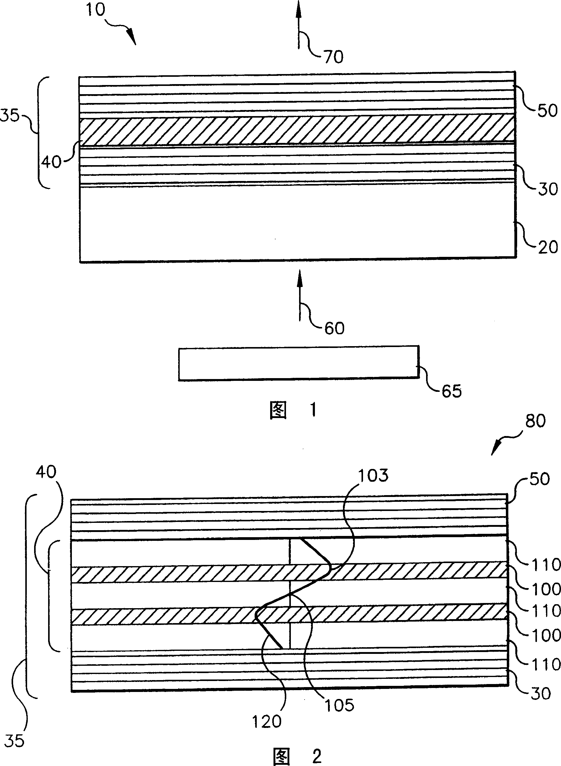
[0035] FIG. 1 shows a schematic diagram of a vertical cavity organic laser device 10 . Substrate 20 can be transparent or opaque, depending on the desired direction of optical pumping and laser emission. The transparent substrate 20 can be transparent glass, plastic or other transparent materials such as sapphire. Alternatively, opaque substrates including, but not limited to, semiconductor materials (eg, silicon) or ceramic materials may be used where optical pumping and emission occur through the same surface. An organic laser thin film structure 35 comprising a first dielectric stack 30 followed by an organic active region 40 and a second dielectric stack 50 is deposited on the substrate. The pump beam 60 emitted by the photon source 65 optically pumps the vertical cavity organic laser device 10 through the first...


PUM

PropertyMeasurementUnit
reflectanceaaaaaaaaaa

Abstract

An electronic imaging system for providing a viewable color image from an image data stream, including: a plurality of different colored laser light sources arranged in an at least one array with each such colored laser light source including a vertical cavity design; at least one area light valve for receiving the laser light and producing the viewable color image from the image data stream; and a projection lens for projecting the viewable color image onto a target plane.

Description

technical field [0001] The present invention relates generally to the field of display or printing systems, and in particular to a display or printing system using area light valves irradiated with laser light. More specifically, the invention relates to the use of arrays of organic laser elements to illuminate area light valves in display or printing systems. [0002] Electrical imaging systems that include light valves that spatially modulate light beams with information are well known in the art. Common uses for such systems include projection display and printing systems. Typically, these systems take the form of a basic white light source, most notably an incandescent or arc lamp, that illuminates one or more light valves or spatial light modulators through appropriate color filtering to form the desired image, which is projected onto a Viewing screen or photosensitive media. Background technique [0003] Laser light is known to be an attractive alternative light sou...

Claims


Application Information

Patent Timeline
Patent Type & Authority Applications(China)
IPC IPC(8): G02F1/13B41J2/455G02F1/00G03B21/00G03B21/14G03G15/00H01S3/08H01S3/0933H01S3/14H01S3/17H01S3/20H04N9/31
CPCH04N9/3161H04N9/3197H04N9/3129H04N9/3155H04N9/3152G03B21/14
Inventor B·E·克鲁施维茨K·B·卡亨A·F·库尔茨J·P·斯庞霍维
Owner EASTMAN KODAK CO
Why Eureka
Try Eureka