
Shape detector

A detection device and detection unit technology, which is applied in the direction of length measurement device, rolling mill control device, tension measurement, etc., can solve the problems of scratches, damage, and deterioration of measurement accuracy of rolled materials

Inactive Publication Date: 2004-10-06
IHI CORP
View PDF5 Cites 3 Cited by
  • Summary
  • Abstract
  • Description
  • Claims
  • Application Information

AI Technical Summary

Problems solved by technology

When the above-mentioned existing shape detection device adds a shape detection function to the existing looper picking device, it is necessary to replace the entire device
[0016] (2) Since the load cell is arranged at the looper strut, the looper strut requires a certain number of separate rolls, so the overall weight of the looper and GD2 become larger, and the responsiveness of the looper control is poor
[0017] (3) Since the length of the looper strut (the length of the lever frame) is relatively large, there is no rigidity in the transverse direction (small camber) when the width of the roll is reduced, and it is easily affected by the transverse shear force of the rolled material, resulting in a decrease in life and a damaged
[0018] (4) The rotation fulcrum of the lever frame and the power measurement point (load measurement point) are exposed, so they change over time in a harsh environment, resulting in deterioration of measurement accuracy
[0019] (5) When the end in the width direction of the rolled material is less than half of the width of the roll, the moment acts on the shape measuring roll to tilt it, reducing the detection accuracy
[0020] (6) The inner circumference of the measured roll is in direct contact with the bearing, and it is easy to conduct heat from the outer circumference of the roll, so the life of the bearing will be reduced due to temperature rise and damage will occur
[0021] (7) Since there is only one load cell for one measuring roll, if the load cell fails, it cannot be measured
When the roll accelerates rapidly from a standstill, it will slip, causing scratches on the rolled material and uneven wear of the roll
If there is uneven wear, it will accelerate the progress of uneven wear and cause poor rotation of the roll
When the roll is not rotating, the temperature difference of the roll will be caused by the cooling water, which will deform the roll and cause the same problem as above.
[0023] (9) It is easy to be affected by the temperature from the rolled material, and the measurement result will cause errors due to temperature changes

Method used


Image

  • Shape detector
  • Shape detector
  • Shape detector

Examples


Embodiment Construction

[0056] Hereinafter, preferred embodiments of the present invention will be described with reference to the drawings. In each figure, common parts are denoted by the same symbols.

[0057] Fig. 6 is an overall perspective view of the shape detection device of the present invention. As shown in the figure, the shape detection device 10 of the present invention is configured to be replaceably installed on a looper roll (not shown) of a looper 2 that controls the tension of the rolled material 1 . In this example, the looper picking device 2 is equipped with a left and right pair of looper support rods 3 with one end supporting the looper roll, and the middle detection between the support fulcrum 3a of the looper support bar 3 and one end of the support looper roll acts on the looper roll. Load cell 4 on the force. Therefore, even if the looper pick-up device 2 is installed on the shape detection device 10 of the present invention by replacing the looper rolls, the load cell 4 c...


PUM


Abstract

In a shape detecting apparatus(10) for controlling tension of a rolled material(1), the shape detecting apparatus comprises a pair of fixing members(12) fixed to both ends of an installation part; a support frame(14) of which both ends are supported by the fixing members, and which is laterally extended; and a plural shape detecting units(20) removably fixed adjacently to the support frame in a width direction of the support frame, wherein the shape detecting unit comprises cylindrical divided rolls(22) contacted with the rolled material, fixing parts(24) fixed to the support frame, arm members(26) of which one end supports the divided roll such that the divided roll is rotatable, and of which the other end is fixed to the fixing parts, and load detectors(28) for detecting the rotation moment acted on the arm members.

Description

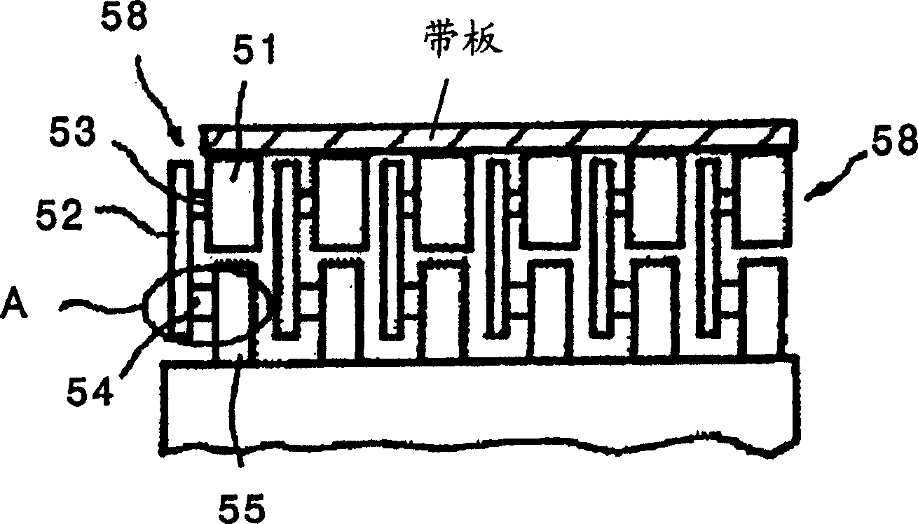
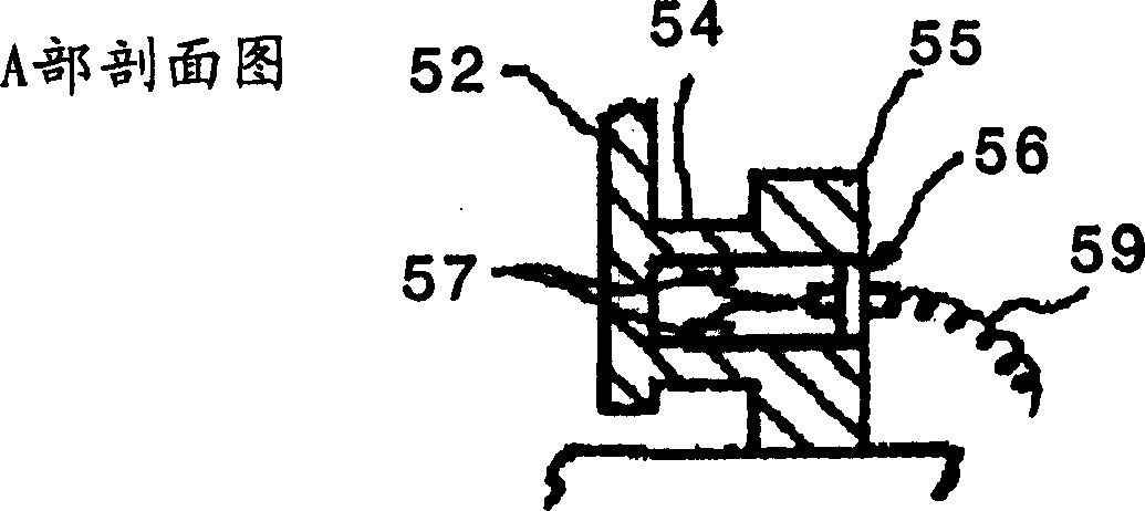
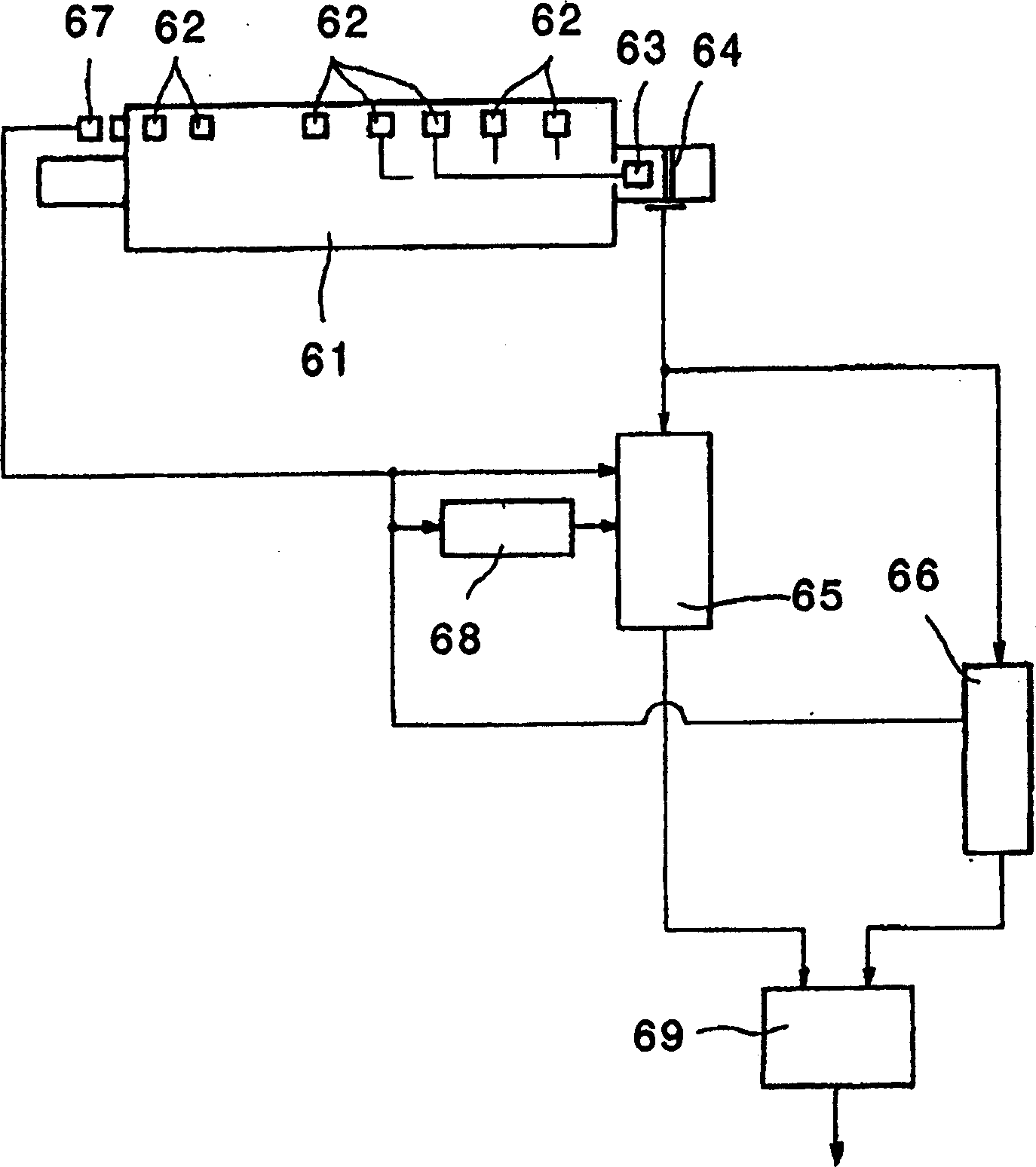
technical field [0001] The present invention relates to a shape detecting device for detecting tension distribution in the width direction in a hot rolling production line and the like. Background technique [0002] Patent Document 1 to Patent Document 5 and the like have disclosed devices for detecting tension distribution in the width direction of a rolling line or the like. [0003] The "shape control device" disclosed in "Patent Document 1" is shown in FIGS. The pin 54 is fixed to the bracket 55 , and a strain gauge such as a strain gauge 57 is provided at the fixing portion 56 to constitute a tension detection element 58 . In the figure, 59 is a wire for drawing out the electric signal (detection signal) of the strain gauge 57 . [0004] The "shape detection device" disclosed in "Patent Document 2" is as shown in Fig. 2. Every time the roll 61 rotates once, when the center of the load detector 62 reaches the vicinity of the position where the roll and the metal plate ...

Claims


Application Information

Patent Timeline
Patent Type & Authority Applications(China)
IPC IPC(8): G01L5/04B21B37/00B21B38/02B21B38/06B21C51/00G01L5/10
CPCB21C51/00B21B38/06G01L5/10B21B38/02
Inventor 井出贤一
Owner IHI CORP
Learn More