Tertiary air duct coal powder preheating and prefiring technique for cement predecomposition kiln

A technology of precalcining kiln and secondary air, which is applied in the field of pulverized coal preheating and precombustion in the tertiary air duct of cement precalcining kiln, which can solve the problems of fuel quality limitations, pipeline and preheater skin blockage, indirect, etc. question

Inactive Publication Date: 2004-10-13
周立秋
View PDF0 Cites 5 Cited by
  • Summary
  • Abstract
  • Description
  • Claims
  • Application Information

AI Technical Summary

Problems solved by technology

If the combustion speed is too slow, the pulverized coal will not burn completely in the furnace, which will easily cause the temperature distribution of the preheater system to be unreasonable, and cause skin blockage of the pipeline and preheater
Therefore, general coal decomposition furnaces have great limitations on fuel quality, especially for low-volatile coal.
In response to this problem, various countries in the world have successively carried out various researches. The main ideas for solving the problem are: appropriately expand the furnace capacity, prolong the residence time of the airflow in the furnace, and improve the structure of the furnace body so that the three-dimensional flow field in the furnace cavity is conducive to improving the gas flow rate. , solid residence time ratio, improve the form, structure and layout of the burner, so that the fuel can be ignited as soon as possible after entering the furnace, and select the furnace type, process flow, layout, etc. according to the needs. Although the above measures can improve to a certain extent, but Due to the failure to consider the problem from the direction of preheating and pre-combustion, it is not direct to increase the combustion speed of pulverized coal, so it only partially solves the problem, but does not fundamentally solve the problem

Method used


Image

  • Tertiary air duct coal powder preheating and prefiring technique for cement predecomposition kiln
  • Tertiary air duct coal powder preheating and prefiring technique for cement predecomposition kiln

Examples


Embodiment Construction

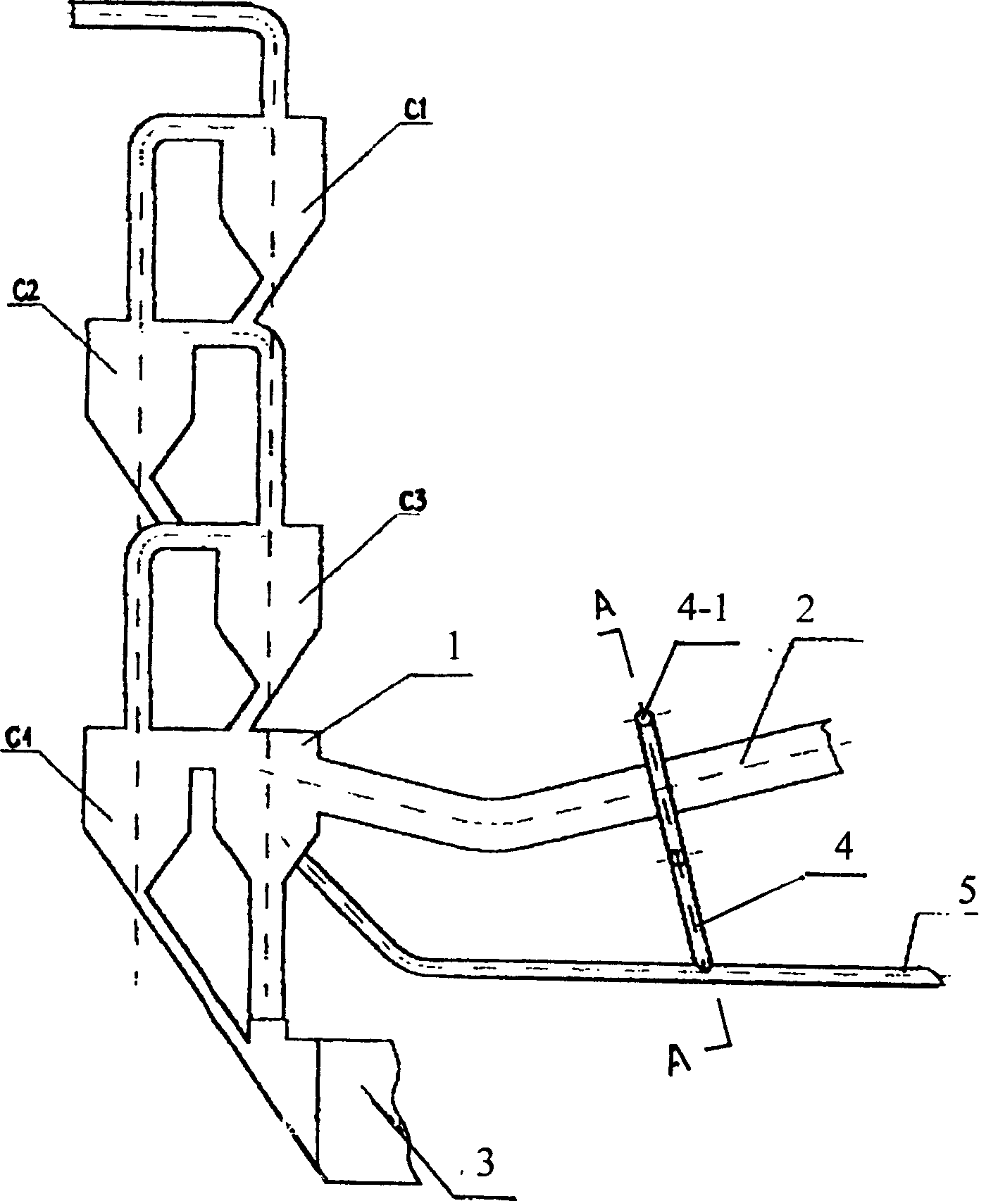
[0016] Such as figure 1 As shown: 3 in the figure is a rotary kiln, and a calciner 1 is set between it and the suspension preheaters C1, C2, C3, and C4 as the second heat source of the system. On the wall of the air duct 2, that is, place A is sprayed into the pulverized coal into the tertiary air duct, so that the pulverized coal and the tertiary hot air enter the calciner together. The pulverized coal is preheated and even pre-combusted during this process, so that when it reaches the calciner, the temperature of the tertiary air reaches 950°C-1000°C. This indicator can be easily achieved by adjusting the distance from A to the tertiary air inlet of the calciner and the ratio range of the pulverized coal entering the tertiary air pipe to the pulverized coal directly entering the calciner. Generally, A is 5-10m away from the tertiary air inlet of the calciner.

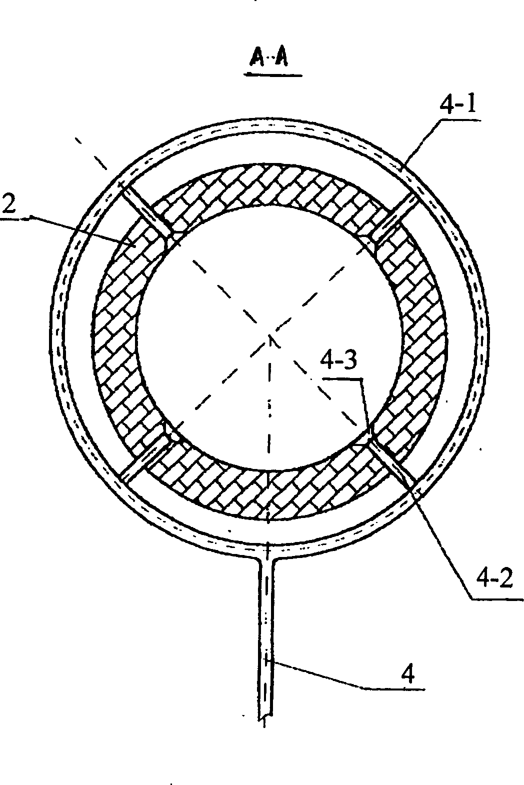
[0017] In order to prevent the impact of the injected coal powder on the wall of the tertiary air duct and the di...


PUM


Abstract

The present invention provides a tertiary air pipe coal powder preheating and preburning technique for cement predecomposition kiln. Between rotary kiln and suspension preheater is st a decomposition furnace as second heat source of said system, the coal powder can be sprayed into the tertiary air pipe according to a certain propoertion from tertiary air pipe wall at a certain distance from tertiary air inlet of decomposition furnace to make the coal powder and tertiary air be together fed into the decomposition furnace. Generally, the coal powder can be sprayed into the tertiary air pipe at a distance 5-10 m from tertiary air inlet of decomposition furnace. The ratio range of the coal powder fed into the tertiary air pipe and the coal powder directly fed into decomposition furnace is 2:8-3:7, and the air-solid ratio of coal powder fed into tertiary air pipe takes that tertiary air temp. of decomposition furnace is reached to 950 deg.C-1000 deg.C as criterion.

Description

technical field [0001] The invention relates to a coal powder preheating and pre-burning technology for the tertiary air duct of a cement precalcining kiln, which belongs to the technical field of new dry process cement clinker firing, and is mainly used to solve the problem that the burning speed of coal powder in the existing calciner is relatively slow and prone to The problem of crust clogging and high requirements on coal quality. Background technique [0002] The precalciner is currently the most advanced process equipment for cement clinker production. A precalciner is added between the rotary kiln and the suspension preheater as the second heat source of the system, so that all the fuel is added from the kiln head in the past. Part of the fuel is added from the kiln head, and part of the fuel is added from the calciner, which improves the heat distribution in the kiln system and moves the most heat-consuming carbonate decomposition process in the clinker calcination ...

Claims


Application Information

Patent Timeline
Patent Type & Authority Applications(China)
IPC IPC(8): C04B7/44
CPCC04B7/434
Inventor 周立秋
Owner 周立秋
Why Eureka
Try Eureka