Angular enclosed battery

A rectangular battery, sealed technology, applied in the direction of battery pack components, battery box/outer, primary battery to battery grouping, etc., can solve the problems of high internal resistance, long connection path, large loss, etc., to reduce connection resistance , easy to connect, ensure the effect of insulation

Inactive Publication Date: 2004-10-20
PANASONIC CORP +1
View PDF0 Cites 11 Cited by
  • Summary
  • Abstract
  • Description
  • Claims
  • Application Information

AI Technical Summary

Problems solved by technology

[0008] However, the above Figure 22 , Figure 23 In the structure shown, although the current conduction path from the positive electrode plate and the negative electrode plate to each lead portion 9a, 9b and the current collector plates 10a, 10b is short, between the current collector plates 10a, 10b, the connecting convex portion 11 at the upper end thereof 1 mutual solder connection between the front ends, thus as Figure 24 As shown by the arrow S in , the connection path is detoured, so the connection path becomes longer. In addition, there is only one connection point, and there is a problem of high internal resistance.
[0009] In addition, as the connection path detours, as shown by the arrow T, more current flows through the plate group 8 in the part between the collector plates 10a and 10b near the connection part, and more current flows in the part far from the connection part. Therefore, the distribution of the current flowing through the plate group 8 becomes uneven, and the entire plate group 8 cannot exert a uniform power generation capacity, and there is a problem of large losses.

Method used


Image

  • Angular enclosed battery
  • Angular enclosed battery
  • Angular enclosed battery

Examples


Embodiment Construction

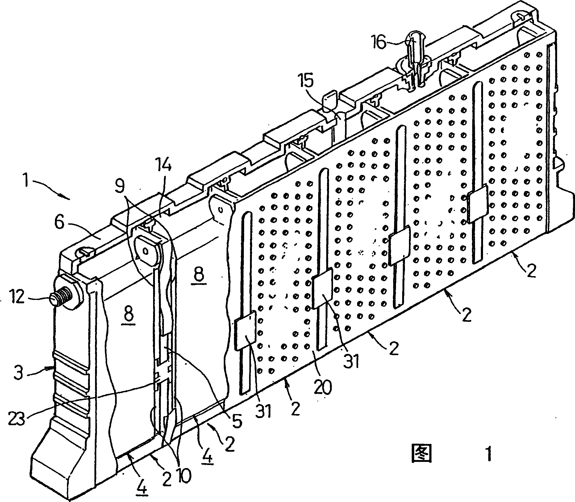
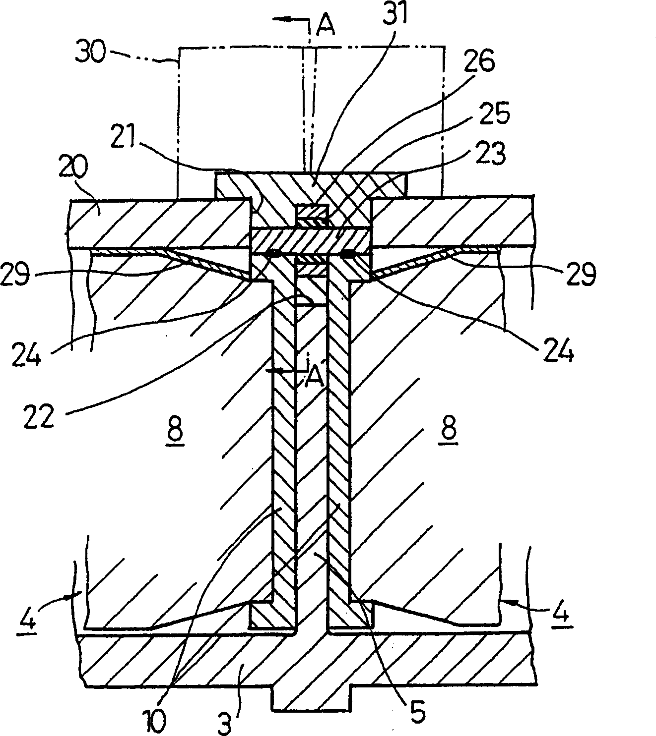
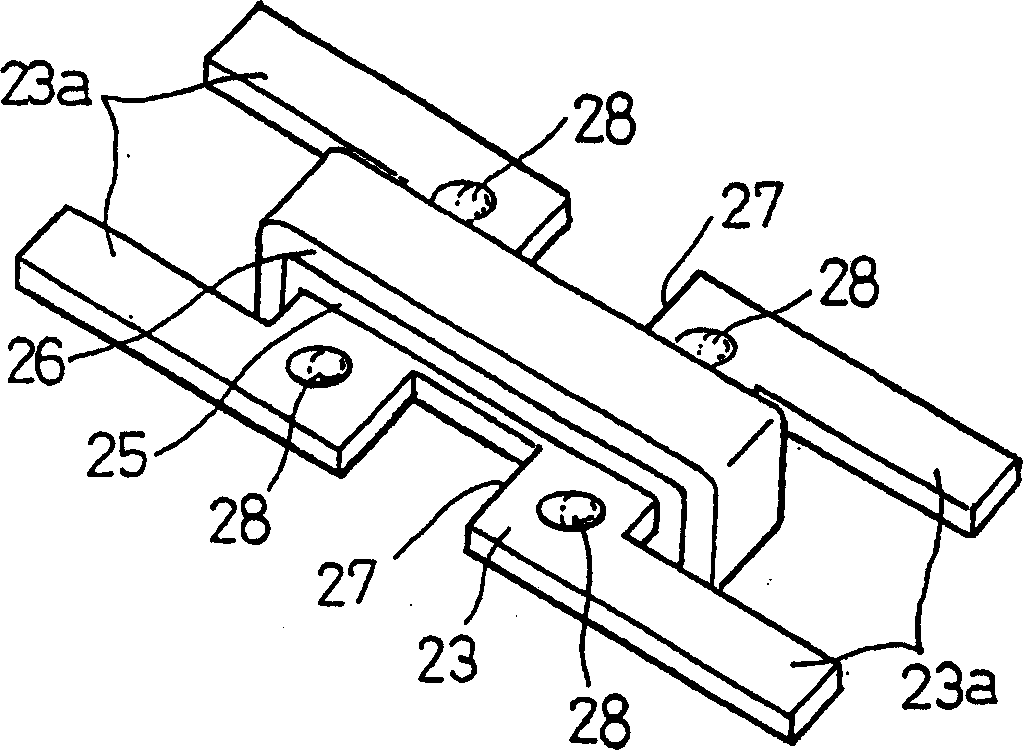
[0055] Hereinafter, refer to Figure 1~ Figure 6 The first embodiment of the rectangular sealed battery of the present invention will be described. However, for the reference Figure 22 , 23 The same components of the conventional technology described are marked with the same reference signs, and the differences are mainly described.

[0056] In FIG. 1, the rectangular battery tank 3 of the rectangular sealed battery 1 of the present embodiment is formed by using a plurality of rectangular parallelepiped battery tanks 4 with narrow short sides and wide long sides as partition walls 5. Shared, so as to be integrally connected to each other. The rectangular battery tank 3 is made of a synthetic resin material such as a composite of PP and PPE, which is resistant to electrolyte. The electrode plate group 8 to which the current collector 10 (10a, 10b) is connected on both sides is accommodated in each battery tank 4 together with electrolyte solution, and the unit cell 2 is comprised....


PUM


Abstract

A prismatic sealed battery has a prismatic battery case (3) which includes a plurality of prismatic containers (4) coupled in a row via partitions (5), electrode plate assemblies (8), and collectors (10) which are joined to lead portions on both sides of the electrode plate assemblies (8). Each container (4) contains the electrode plate assembly (8) to which said collectors 10 are joined. An opening (21) is formed in at least one side wall (20) of the prismatic battery case (3) and in a position where each partition (5) is disposed, in such a manner as to face the containers (4) on both sides, and a conductive connection member (23) disposed in the opening (21) is connected to the collectors (10, 10) on both sides of the partition (5). Since the current-carrying path between the electrode plate assemblies (8) becomes short, internal resistance decreases, and hence internal resistance per cell (2) is reduced. Even and full use of the whole electrode plate assembly (8) achieves higher power output.

Description

Technical field [0001] The present invention relates to a rectangular sealed battery, and more particularly, to a rectangular sealed battery that realizes a reduction in internal resistance in a collective storage battery formed by connecting a plurality of single cells. Background technique [0002] In order to obtain the required power capacity, a conventional collective storage battery formed by connecting a plurality of single cells, a plurality of single rectangular parallelepiped single cells are arranged such that the wide and long sides of the battery slot overlap each other. , The end plates are arranged outside the battery slots of the cells at both ends, and they are integrally connected by tying them with straps. In addition, in each single cell, a lead is drawn upward from the upper end of the electrode plate, and it is installed on the battery slot cover The terminals are connected, and the terminals are connected to each other through the connecting plate between t...

Claims


Application Information

Patent Timeline
Patent Type & Authority Applications(China)
IPC IPC(8): H01M6/42H01M50/112H01M50/176H01M50/529H01M50/534H01M50/548H01M50/553
CPCY02E60/12H01M2/24H01M2/0217H01M2/0242H01M2/021H01M2/06H01M6/42H01M2/266H01M50/103H01M50/112H01M50/529H01M50/534H01M50/553H01M50/176H01M50/548H01M50/531
Inventor 加治屋弘海唐泽昭司大西正人朝比奈孝浜田真治江藤丰彦
Owner PANASONIC CORP
Why Eureka
Try Eureka