

Multifunctional power supply system of solar energy
A power supply system and solar battery technology, applied in the field of multifunctional solar power supply systems, can solve the problems of one-way transmission of energy and low efficiency, and achieve the effect of solving one-way transmission of energy, high efficiency and low efficiency
- Summary
- Abstract
- Description
- Claims
- Application Information
AI Technical Summary
Problems solved by technology
Method used
Image

Examples
Embodiment 1
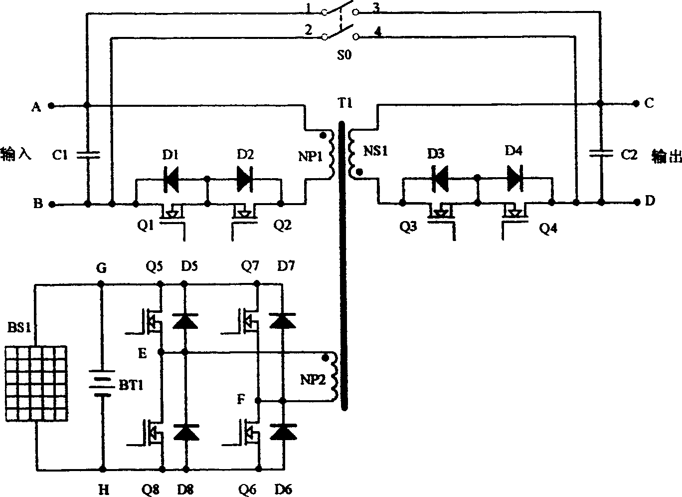
[0018] Embodiment 1 of the present invention is as figure 2 As shown, including solar cells, storage batteries, high-frequency isolation transformer T1, field effect transistors Q1-Q8, diodes D1-D8, capacitors C1 and C2 and double-pole single-throw switch S0, where high-frequency isolation transformer T1 consists of three windings NP1 , composed of NP2 and NS1.
[0019] The input terminals A and B of Embodiment 1 of the present invention are directly connected to the power grid, and one end of the capacitor C1, the terminal with the same name of the winding NP1 of the high-frequency transformer (marked with a black dot in the figure) is connected to the input terminal 1 of the double-pole single-throw switch S0 At the input terminal A; the other terminal of the capacitor C1, the drain of the field effect transistor Q1, the cathode of the diode D1 and the input terminal 2 of the double pole single throw switch S0 are connected to the input terminal B; the anodes of the diodes ...
Embodiment 2
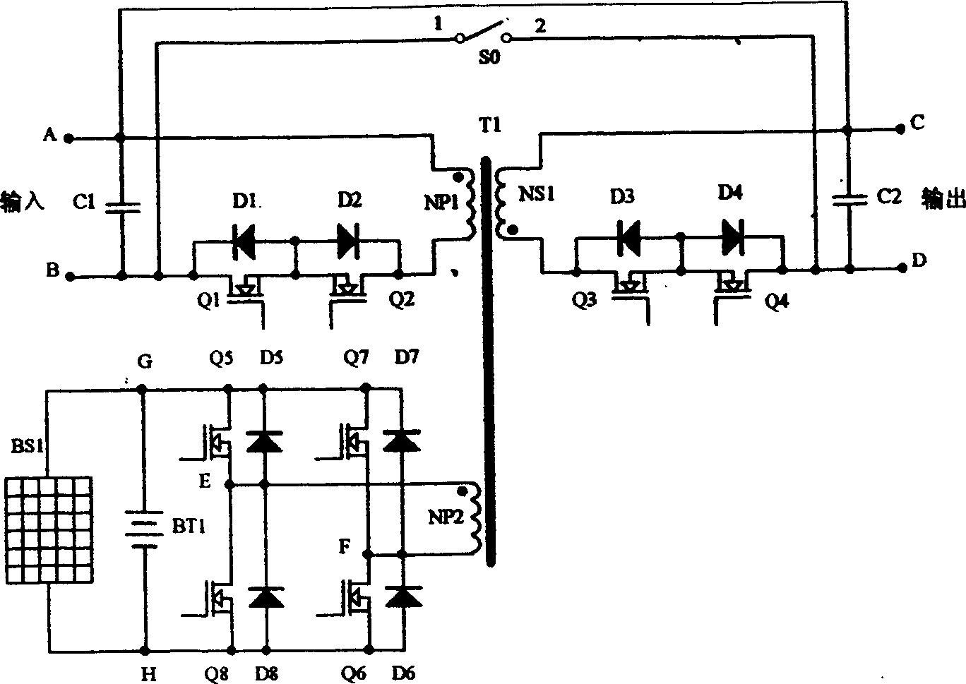
[0026] Embodiment 2 of the present invention is as image 3 As shown, including solar cells, storage batteries, high-frequency isolation transformer T1, field effect transistors Q1-Q8, diodes D1-D8, capacitors C1 and C2 and SPST switch S0, where the high-frequency isolation transformer T1 consists of three windings NP1, NP2 and NS1 composition.
[0027] The input terminals A and B of Embodiment 2 of the present invention are directly connected to the power grid, and one end of the capacitor C1 is connected to the terminal of the same name (marked with black electricity in the figure) of the winding NP1 of the high-frequency transformer to the input terminal A, and the input terminal A is connected to the output terminal. C is directly connected; the other end of the capacitor C1, the drain of the field effect transistor Q1, the cathode of the diode D1 and the input terminal 1 of the single-pole single-throw switch S0 are connected to the input terminal B; the anodes of the dio...
Embodiment 3
[0031] Embodiment 3 of the present invention is as Figure 4 As shown, including solar cells, storage batteries, high-frequency isolation transformer T1, field effect transistors Q1-Q8, diodes D1-D8, capacitors C1 and C2 and SPST switch S0, where the high-frequency isolation transformer T1 consists of three windings NP1, NP2 and NS1 composition.
[0032] The input terminals A and B of Embodiment 3 of the present invention are directly connected to the power grid, and one end of the capacitor C1, the terminal with the same name of the winding NP1 of the high-frequency transformer (marked with black electricity in the figure) and the input terminal 1 of the single-pole single-throw switch S0 are connected to each other. Input A,; the other end of the capacitor C1, the drain of the field effect transistor Q1 and the cathode of the diode D1 are connected to the input B, and the input B is directly connected to the output D; the anodes of the diodes D1 and D2, and the field effect ...
PUM
 Abstract
Description
Claims
Application Information