Ultrasonic Doppler diagnosis system with automatic following function

A technology of ultrasonic diagnosis and color Doppler, which is applied in the directions of acoustic wave diagnosis, infrasonic wave diagnosis, ultrasonic/sonic wave/infrasonic wave diagnosis, etc. It can solve problems such as difficult diagnosis, large sampling volume of Doppler signal, and increased ultrasonic irradiation dose, and achieve Effects of improving inspection efficiency, reducing interference factors, and reducing exposure dose

Inactive Publication Date: 2004-11-03
王作军
View PDF4 Cites 9 Cited by
  • Summary
  • Abstract
  • Description
  • Claims
  • Application Information

AI Technical Summary

Problems solved by technology

[0007] However, there are still shortcomings in these two technologies, that is, if the movement range of the blood vessel of interest is large, the sampling volume that needs to be simultaneously detected at the same sampling frequency for its Doppler signal may be too large, which not only increases the performance of the system by a lot of hardware and software , and the dose of ultrasound radiation received by the patient may also increase
Moreover, if the movement of the blood vessel of interest is large, with the expansion of the detection area, the sampling volume or the selection of the sampling volume is more likely to be interfered by other irrelevant blood flows, which may cause difficulties in diagnosis and even errors

Method used


Image

  • Ultrasonic Doppler diagnosis system with automatic following function
  • Ultrasonic Doppler diagnosis system with automatic following function
  • Ultrasonic Doppler diagnosis system with automatic following function

Examples


Embodiment Construction

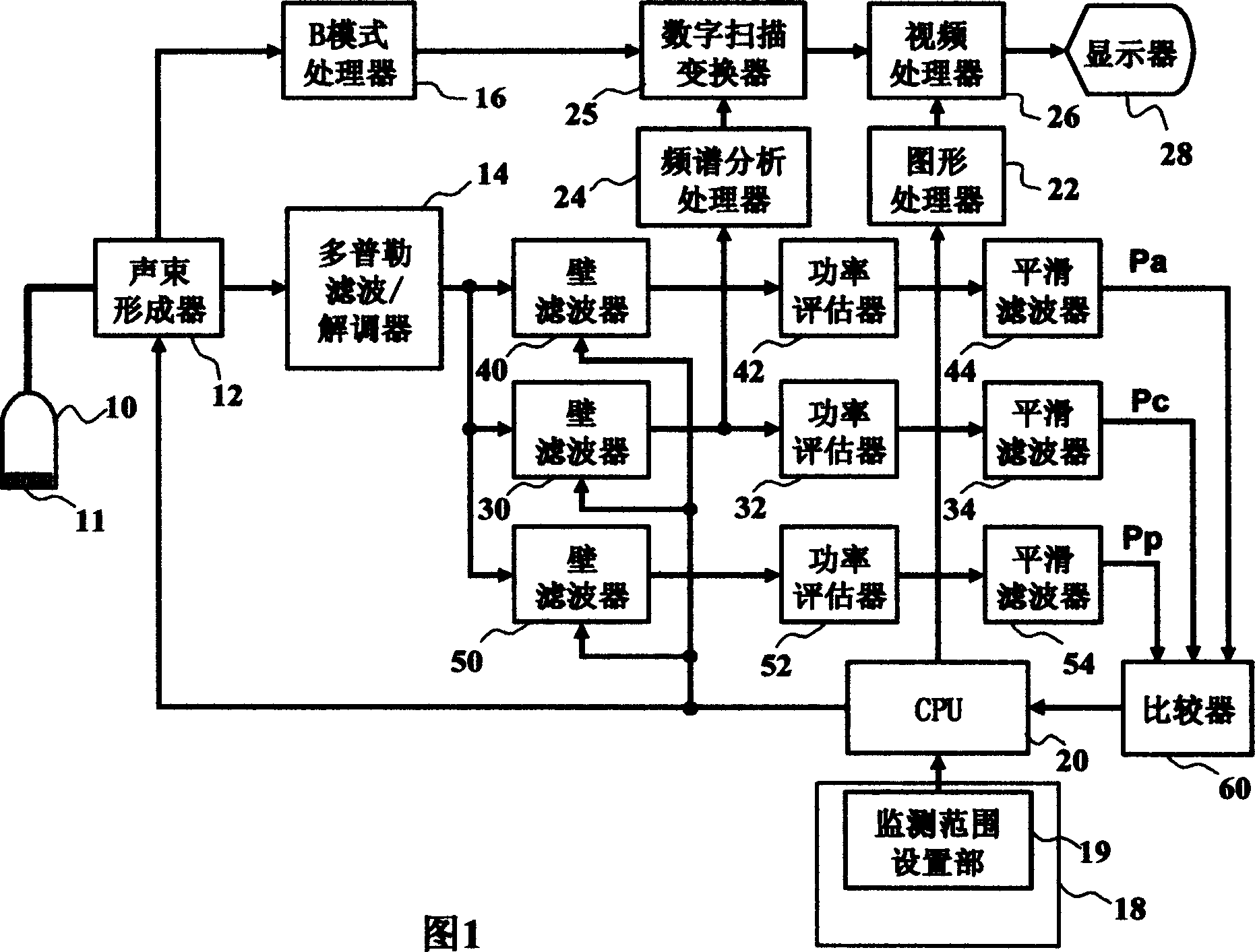
[0020] Fig. 1 is a structural block diagram of an embodiment of an ultrasonic diagnostic system constructed according to the present invention. Among them, a probe 10 is included, which is used to transmit ultrasonic pulse beams into a subject's body and receive echo information returned from the body. The direction in which the ultrasonic pulse beam enters the body can be changed by mechanically moving the transducer inside or by using electronically controlled scanning of the multi-element array transducer 11 . The probe 10 converts the received echo information into an electrical signal and sends it to an acoustic beam former 12 . As is well known in the art, the acoustic beamformer 12 delays the echo signals from the individual elements of the transducer 11 by varying lengths of time and sums them to form an echo signal from a particular return direction. Focus on the enhanced echo signal. This return direction is hereinafter referred to as the direction line of the echo...


PUM


Abstract

The ultrasonic diagnosis system capable of tracking blood flow position automatically to obtain the spectral Doppler information has measures of setting one limited monitoring range and obtaining the Doppler information of sampling volumes inside the range. The system compares the Doppler information of the sampling volumes to select one standard sampling volume and regulates the position of the limited monitoring range around the selected sampling volume to realize the automatic tracking of the blood flow. Spectral curve is formed and displayed based on the Doppler information for the calculation of various blood flow parameters. Optimally, the system can display the limited monitoring range and the position of the central sampling volume dynamically in image of mode B or other spatial display mode.

Description

technical field [0001] The invention relates to detecting and diagnosing the fluid flow state in the body by using the ultrasonic Doppler technology, in particular to detecting the flow state of blood or other body fluids by using the ultrasonic spectrum Doppler technology. Background technique [0002] Ultrasonic diagnostic systems have long been applied to detect the flow of body fluids such as blood by using the Doppler principle. Typically, a series of ultrasound pulses are sent into a blood vessel or other measurement site in the body. Echo signals returning from the measurement site are individually compared with a phase reference signal to determine the frequency shift of the echoes. The Doppler frequency shift is proportional to the component of the liquid velocity in the direction of the sound beam. One existing way of displaying this Doppler information is to display its time-frequency representation graphically in real time. This display mode is generally calle...

Claims


Application Information

Patent Timeline
Patent Type & Authority Applications(China)
IPC IPC(8): A61B8/00A61B8/06
Inventor 王作军曹铁生段云友蒋姗姗
Owner 王作军
Why Eureka
Try Eureka