LED device and portable telephone, digital camera and LCD apparatus using the same

A LED device and device technology, applied in the direction of electric solid-state devices, semiconductor devices, chemical instruments and methods, etc., can solve the problems of narrow peak emission width, difficulty in obtaining bright white light with color reproduction characteristics, etc.

Inactive Publication Date: 2004-11-03
SHARP KK
View PDF2 Cites 16 Cited by
  • Summary
  • Abstract
  • Description
  • Claims
  • Application Information

AI Technical Summary

Problems solved by technology

[0006] But in this white LED device, the width of the peak emission of each light-emitting element is narrow, so it is difficult to obtain bright white light with satisfactory color reproduction characteristics

Method used


Image

  • LED device and portable telephone, digital camera and LCD apparatus using the same
  • LED device and portable telephone, digital camera and LCD apparatus using the same
  • LED device and portable telephone, digital camera and LCD apparatus using the same

Examples


Embodiment 1

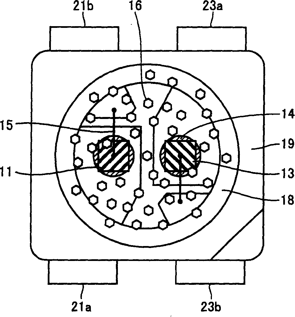
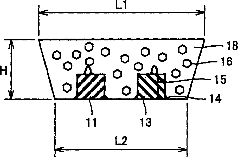
[0057] refer to Figure 1A and 1B , use InGaN with a peak emission wavelength of 460nm as the blue light emitting element, InGaN is on the SiC substrate, the electrodes are arranged in a P / N vertical relative arrangement, and AlGaInP with a peak emission wavelength of 624nm and a P / N vertical relative arrangement is used as the The red light emitting element 13 uses SrGa with an average particle diameter of 8 μm 2 S 4 : Eu as the green fluorescent substance 16. The terminal electrodes 21a, 21b, 23a, and 23b are Cu alloys, and for better wire bonding, the Cu alloys are plated with Au plating. Ag paste was used as the conductive adhesive 14 , and Au wire was used as the bonding wire 15 . The light-transmitting resin 18 is thermosetting epoxy resin (specific gravity: 1.2).

[0058] Figure 1A and 1B The shown LED device was fabricated through the following steps. First, the n-electrodes of the blue light emitting element 11 and the red light emitting element 13 are bonded t...

Embodiment 2

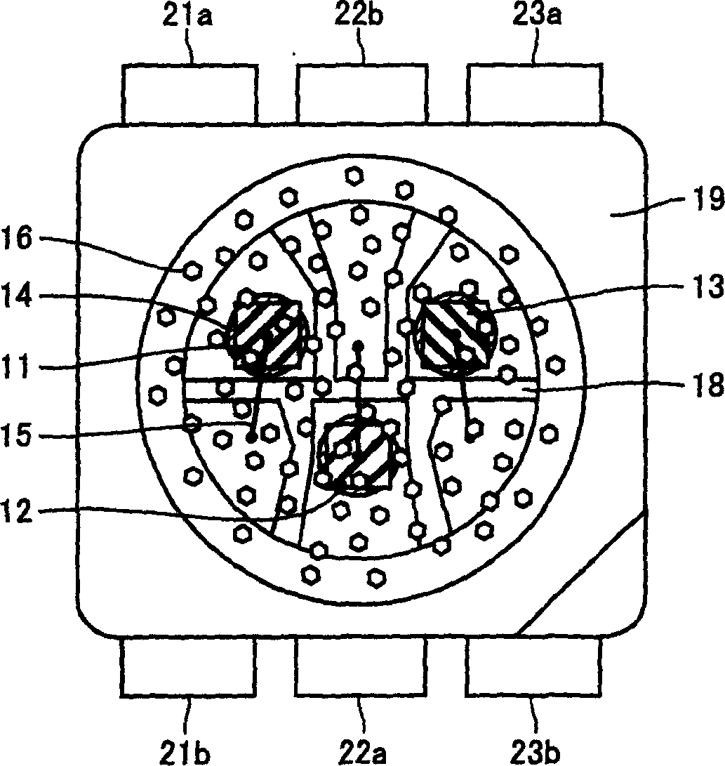
[0065] refer to Figure 2A and 2B , using GaN with a peak emission wavelength of 405nm and electrodes in a P / N vertically opposite arrangement as the ultraviolet / violet light emitting element 12 . The red light emitting element 13, the green fluorescent substance 16, the terminal electrodes 21a, 21b, 23a, and 23b, the conductive adhesive 14, the bonding wire 15, and the light-transmitting resin 18 are the same as those used in Embodiment 1. The LED device was fabricated by the steps similar to that of Example 1.

[0066] In this LED device, when only using 35mA current to drive the red light emitting element 13, the axial luminous intensity of the red light obtained is 1.1cd; For fluorescence, blue-green light with an axial luminous intensity of 1.1cd is obtained. When only 35mA current is used to drive the ultraviolet / violet light emitting element 12, green light with an axial luminous intensity of 2.0cd from the green fluorescent substance 16 is obtained. , and when these...

Embodiment 3

[0068] Adopt and embodiment 2 similar ways to manufacture LED device, just use SrAl 2 o 4 :Eu instead of SrGa 2 S 4 : Eu is used as the green fluorescent substance 16, and 0.1 g of the green fluorescent substance is kneaded in every 1 g of light-transmitting resin.

[0069] In this LED device, when only 35mA current is used to drive the red light emitting element 13, the axial luminous intensity of the obtained red light is 1.1cd; when only 35mA current is used to drive the blue light emitting element, the green fluorescent substance is hardly excited. Obtained is the blue light with an axial luminous intensity of 0.5cd. When only 35mA current is used to drive the ultraviolet / violet light emitting element 12, what is obtained is the green light with an axial luminous intensity of 1.4cd emitted by the green fluorescent substance 16, and when these When the light-emitting elements are all driven by a current of 35 mA, white light with an axial luminous intensity of 3.0 cd and...


PUM

PropertyMeasurementUnit
wavelengthaaaaaaaaaa
sizeaaaaaaaaaa
diameteraaaaaaaaaa

Abstract

An LED device at least including a blue light emitting element having peak emission wavelength of 420 nm to 480 nm, a green fluorescent substance having peak wavelength of fluorescent spectrum in the range of 500 nm to 580 nm with the emission of the blue light emitting element, and a red light emitting element having peak emission wavelength of 600 nm to 670 nm is provided. The device may further include an ultraviolet / violet light emitting element for exciting green fluorescent substance. As a result, an LED device capable of attaining bright white light with good color reproduction characteristic is provided.

Description

[0001] This non-provisional application is based on Japanese Patent Application No. 2003-115987 filed with the Japan Patent Office on April 21, 2003, the entire contents of which are hereby incorporated by reference. technical field [0002] The present invention relates to an LED (Light Emitting Diode) device, which is used as an auxiliary light source for a CCD (Charge Coupled Device) or CMOS (Complementary Metal Oxide Semiconductor) camera, or as a backlight source for an LCD (Liquid Crystal Display) . More particularly, the present invention relates to an LED device having excellent color reproduction characteristics and emitting bright white light, the device including a combination of a light emitting element and a fluorescent substance excited by the light emitting element. Background technique [0003] As a conventional white light-emitting device using an LED, there is known a white LED device (see, for example, Japanese Patent Laid-Open No. 2002-064220) which inclu...

Claims


Application Information

Patent Timeline
Patent Type & Authority Applications(China)
IPC IPC(8): G02F1/13357C09K11/08C09K11/54C09K11/56C09K11/58C09K11/59C09K11/62C09K11/64C09K11/66C09K11/77C09K11/80H01J1/62H01L25/075H01L33/44H01L33/50H01L33/56H04N5/225H04N101/00
CPCC09K11/7729H04N5/2256C09K11/595H01L33/504H01L2224/45144H01L33/502C09K11/7734Y02B20/181H01L2224/48091C09K11/7792C09K11/662C09K11/54H01L2224/48247C09K11/62H01L25/0753C09K11/584C09K11/0883H01L2224/48465H01L2924/181Y02B20/00H04N23/56H01L2924/00014H01L2924/00H01L2924/00012
Inventor 尾本雅俊增田昌嗣北野雅阳
Owner SHARP KK
Why Eureka
Try Eureka